English
 中文简体
中文简体 русский
 Español
 Deutsch

What Is an Elevator Over-speed Governor?
Content
- 1 The Mechanics Behind Safety
- 2 Classifying Speed Monitoring Devices
- 3 Specific Applications in Vertical Transport
- 4 Maintenance and Diagnostic Protocols
- 5 FAQ
- 5.1 What is the standard tripping speed for an Elevator Over-speed Governor?
- 5.2 Why is the centrifugal overspeed governor mechanism preferred over electronic sensors?
- 5.3 How do I know if I need a hydraulic elevator overspeed governor for my building?
- 5.4 What are the signs that I need to perform elevator overspeed governor troubleshooting?
- 5.5 Can I learn how to test elevator over-speed governor myself, or must I hire a contractor?
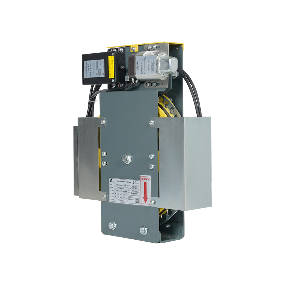
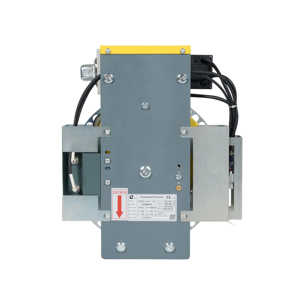
In the vertical transportation industry, safety remains the paramount concern for engineers, architects, and property managers. Among the myriad of safety components within an elevator system, one stands out as the final line of defense against catastrophic free-fall accidents. The Elevator Over-speed Governor is a precision mechanical device designed to monitor the speed of the elevator car or counterweight. If the car exceeds a predetermined speed, typically set at 115% of the rated speed, the governor triggers a mechanical switch that activates the safety gear, clamping the guide rails and bringing the elevator to an immediate halt. This mechanism operates independently of the elevator's primary electrical control system, ensuring a mechanical fail-safe that functions even during power failures or electrical shorts. Understanding the intricacies of this device is essential for modernizing aging infrastructure and ensuring compliance with evolving international safety codes such as EN 81 and ASME A17.1. The reliability of these systems depends heavily on precision manufacturing and rigorous testing protocols. Shanghai Liftech Elevator Accessories Co., Ltd., established in 2004, is a specialized enterprise dedicated to the R&D, manufacturing, testing, and sales of these critical elevator safety components. With over two decades of sustained development, Liftech has established itself as a leading manufacturer in China's elevator safety sector, providing high-quality products and solutions to a wide range of major elevator brands and engineering clients across domestic and international markets, ensuring that every installation meets the highest standards of public safety.
The Mechanics Behind Safety
Centrifugal Overspeed Governor Mechanism
At the heart of most modern elevator safety systems lies the centrifugal overspeed governor mechanism. This ingenious device operates on the fundamental principles of rotational dynamics and centrifugal force. As the elevator sheave rotates, it drives the governor pulley. Inside the pulley housing, flyweights or flyballs are attached to a spinning spindle. When the elevator runs at normal speed, the tension of a spring holds these flyweights in a retracted position. However, should the rotational velocity exceed the set limit, the centrifugal force acting on the flyweights overcomes the spring tension, causing them to swing outward. This outward movement is physically linked to a locking mechanism. Once the flyweights swing out to a specific point, they trip a roller catch, which then actuates a linkage system to trip the electrical switch first, cutting power to the motor, and subsequently pulling the rope connected to the safety gear. This seamless transition from rotational monitoring to linear actuation is the hallmark of effective safety engineering, requiring tolerances measured in microns during the manufacturing process.
- Activation relies on calibrated spring tension to determine the precise tripping speed.
- Centrifugal force provides a passive, physics-based means of detection that does not require external power.
- The mechanism must be isolated from environmental contaminants like dust and moisture to prevent friction jamming.
Classifying Speed Monitoring Devices
Elevator Overspeed Governor Types
Selecting the correct safety apparatus requires a deep understanding of the elevator overspeed governor types available on the market. While the fundamental principle of speed monitoring remains consistent, the mechanical configurations vary significantly based on the rated speed, load capacity, and traction method of the elevator. Broadly speaking, governors can be classified by their axis of rotation (axial vs. radial) or their actuation method (centrifugal vs. pneumatic). Axial governors are often used in high-speed applications because they offer superior stability at high rotational velocities. Radial governors, while more common in medium to low-speed elevators, are robust and easier to maintain. Furthermore, the design differs between traction elevators, where the governor rope is connected to the car frame, and hydraulic systems, where the integration points differ significantly due to the direct-acting nature of the plunger. Understanding these distinctions allows procurement officers and safety inspectors to specify the exact component required for their specific elevator architecture.
| Governor Type | Best Application | Speed Range | Key Characteristic |
| Axial Flow Governor | High-speed Traction Elevators | 2.5 m/s to 10.0 m/s+ | Superior balance at high RPMs; complex design. |
| Radial Governor | Low/Medium Speed Elevators | 0.63 m/s to 2.5 m/s | Simplified maintenance; robust construction. |
| Pneumatic Governor | Specialized/Heavy Duty | Variable | Uses air pressure; rare in modern commercial setups. |
Specific Applications in Vertical Transport
Hydraulic Elevator Overspeed Governor
While traction elevators are the primary focus for speed governors, hydraulic elevator overspeed governor systems present unique engineering challenges and solutions. Unlike traction elevators which hang by ropes, hydraulic elevators are supported by a piston plunger moved by fluid pressure from a power unit. Consequently, the risk of uncontrolled descent stems from a failure in the hydraulic piping or control valves rather than a traction rope failure. In these systems, the governor is often directly mounted to the cylinder or driven by a separate wire rope attached to the car. If the car descends too quickly, the governor triggers a safety device attached directly to the plunger or the cylinder body, which mechanically clamps the plunger to stop the movement. This is crucial because a hydraulic failure can result in a "runaway" condition where fluid bypasses the control valve unchecked.
- Direct-acting governors are mounted on the cylinder head, saving space in the pit.
- They incorporate a pipe rupture valve which is integrated with the governor linkage for immediate shut-off.
- Must be synchronized with the buffer performance to ensure a smooth stop in the pit.
Maintenance and Diagnostic Protocols
How to Test Elevator Over-speed Governor
Regular safety audits are mandated by law, and knowing exactly how to test elevator over-speed governor systems is a critical competency for maintenance technicians. Testing involves simulating an over-speed condition in a controlled environment to verify that the electrical switch trips before the mechanical trip point, and that the mechanical linkage activates the safety gear effectively. The procedure typically involves isolating the elevator, running it at a reduced inspection speed, and manually tripping the governor mechanism using a specialized tool to observe the reaction. Alternatively, a "no-load" test may be performed with the car empty, carefully monitoring the speed indicators. Modern regulations often require periodic electrical tripping tests and less frequent, yet mandatory, mechanical tripping tests where the safety gear actually clamps the rails. These rigorous protocols ensure that the friction surfaces, springs, and linkages have not degraded due to fatigue or corrosion over time.
- Electrical Trip Test: Verifies that the main contactor opens and the motor stops when rated speed is exceeded by 10%.
- Mechanical Trip Test: Verifies that the governor rope actuates the safety gear mechanism at 115% of rated speed.
- Reset Test: Ensures the governor can be easily reset and that the safety gear releases without manual force.
Elevator Overspeed Governor Troubleshooting
Even with precision manufacturing, field conditions can lead to operational issues necessitating expert elevator overspeed governor troubleshooting. Common problems include false tripping, where the governor activates at normal speeds, or failure to trip at all. False tripping is frequently caused by contamination in the governor pulley bearings or a loss of tension in the governor rope due to stretching or misalignment. Vibration and noise are also early indicators of bearing wear or misalignment between the governor sheave and the traction sheave. In more severe cases, corrosion can seize the internal flyweights, preventing them from moving outward when required, which renders the safety device inoperative. Troubleshooting these systems requires a systematic approach, checking the rope tension, lubricating the moving parts according to the manufacturer's specifications, and inspecting the switch contacts for pitting or carbon buildup.
| Symptom | Potential Cause | Corrective Action |
| False Tripping | Road vibration or loose rope tension | Adjust rope tension; check shock absorbers. |
| Governor Vibration | Worn bearings or misalignment | Replace bearings; realign sheave grooves. |
| Failure to Trip | Seized flyweights or rust | Clean and lubricate internal mechanism; replace if worn. |
FAQ
What is the standard tripping speed for an Elevator Over-speed Governor?
The standard tripping speed for the mechanical activation of the governor is typically set at 115% of the elevator's rated speed. The electrical switch, which cuts power to the motor, is designed to trip slightly earlier, usually at around 110% of the rated speed. This sequence ensures that the motor is powered down before the mechanical safety gear engages, reducing wear on the braking system.
Why is the centrifugal overspeed governor mechanism preferred over electronic sensors?
While electronic sensors are used for monitoring, the centrifugal overspeed governor mechanism is a purely mechanical device that does not rely on external power sources or software logic. This makes it fail-safe; in the event of a total power blackout or electrical system failure, the centrifugal force generated by the rotation will still physically trigger the safety gear, ensuring the elevator stops regardless of the electrical status.
How do I know if I need a hydraulic elevator overspeed governor for my building?
Most local safety codes, such as ASME A17.1, require a speed-sensing device for hydraulic elevators where the rated speed exceeds a certain threshold (often 0.75 m/s or 150 ft/min). If your hydraulic elevator is direct-acting and travels at speeds that could cause injury or plunger damage in the event of a control valve failure, a hydraulic elevator overspeed governor is mandatory to comply with safety regulations.
What are the signs that I need to perform elevator overspeed governor troubleshooting?
Signs that you need to perform elevator overspeed governor troubleshooting include unusual noises coming from the machine room, the elevator stopping abruptly without cause, or the safety gear switch light illuminating on the controller panel. Physical inspection may reveal excessive rust on the governor rope, oil contamination on the governor pulley, or fraying of the wire rope attached to the tension pulley.
Can I learn how to test elevator over-speed governor myself, or must I hire a contractor?
While the theory of how to test elevator over-speed governor systems can be studied, actual testing must be performed by certified elevator technicians. The process involves working with moving heavy machinery and bypassing normal safety controls, which poses significant risks. Moreover, safety codes often require that these tests be witnessed and signed off by a qualified inspector to certify the elevator for public use.