English
 中文简体
中文简体 русский
 Español
 Deutsch

Are Your Elevator Safety Components Truly Compliant?
Content
- 1 1. The Overspeed Governor: The Primary Arresting System
- 2 2. Door Lock Systems & Safety Gear: Preventing Entrapment and Freefall
- 3 3. Brakes & Valves: Ensuring Controlled Stops and Hydraulic Safety
- 4 4. A Framework for Compliant Procurement & Lifecycle Management
- 5 FAQ
- 5.1 How often should elevator safety components be tested according to current codes?
- 5.2 What are the risks of using non-OEM or uncertified replacement safety parts?
- 5.3 What is the difference between a Type Test and a Routine Test for components?
- 5.4 Can you explain the process for testing elevator car safety gear?
- 5.5 What key specifications are vital when replacing a hydraulic elevator safety valve?
The integrity of any vertical transportation system relies on a silent, non-negotiable pact of safety. This safety is not an abstract concept but the precise, reliable function of a suite of critical, interdependent mechanical and electrical parts. For elevator consultants, facility managers, and maintenance directors, ensuring compliance goes beyond possessing a certificate; it demands a deep technical understanding of the design, performance thresholds, and lifecycle management of each elevator safety component. A failure in a single, seemingly minor part can compromise an entire system's safety envelope. This guide serves as a technical deep dive into the core safety subsystems, offering a framework for evaluating compliance, specifying replacements, and implementing a proactive maintenance strategy. It is based on the principle that true safety is engineered into every component, a philosophy championed by specialized manufacturers with decades of dedicated R&D, such as Shanghai Liftech Elevator Accessories Co., Ltd., whose focus on precision manufacturing supports major global brands and engineering firms in upholding the highest safety standards.
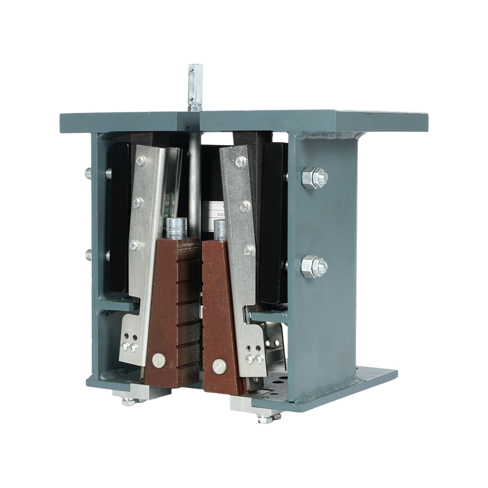
1. The Overspeed Governor: The Primary Arresting System
The overspeed governor is the cornerstone of traction elevator safety, acting as the initiator of the car-arresting sequence. Its function is purely mechanical and fail-safe: to detect when the elevator car exceeds its predetermined rated speed by a critical margin (typically 115-140%) and to mechanically trigger the car safety gear. Modern governors utilize a centrifugal flyweight mechanism connected to a governor rope. As speed increases, centrifugal force causes the flyweights to overcome a spring tension, engaging a latch mechanism that locks a sheave. This sudden stop of the governor rope, which is connected to the safety gear lever in the car, initiates the safety gear activation. Compliance with standards like EN 81-20/50 and ASME A17.1 is paramount, mandating rigorous type testing for tripping speed, structural strength, and durability. For procurement teams searching for an elevator overspeed governor for sale, the listing price is a secondary concern. The primary focus must be on documented certification for the specific elevator speed and load rating, material traceability for critical forgings, and the availability of original factory test reports that validate its performance curve. A non-compliant or poorly calibrated governor is a single point of catastrophic failure.
- Key Compliance Checkpoints: Verify the governor's certified speed range matches your elevator's rated speed and the diameter of your governor rope. The tripping speed must be documented and sealed at the factory.
- Maintenance Protocol: Functional testing must be performed quarterly by manually simulating an overspeed condition to ensure the governor trips and activates the safety gear linkage without binding.
- Technical Documentation: Always request the original type-test certificate and installation manual. The unit should have a clear, indelible marking with its serial number, rated speed, and rope diameter.
| Evaluation Factor | Low-Risk/Compliant Component | High-Risk/Non-Compliant Indicator |
| Certification | Full EN 81 or ASME A17.1 type-test certificate from a recognized lab, matching elevator specs. | Only a generic "CE" mark or self-declaration of conformity with no supporting test reports. |
| Trigger Mechanism | Precision-machined flyweights and latches with corrosion-resistant finishes, smooth operation. | Signs of pitting, corrosion, or wear on contacting surfaces; sticky or hesitant movement. |
| Documentation | Complete dossier including test reports, material certificates, and installation/calibration instructions. | Minimal or photocopied paperwork, lacking traceable serial numbers or specific speed data. |
2. Door Lock Systems & Safety Gear: Preventing Entrapment and Freefall
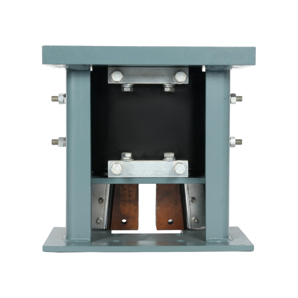
Elevator safety is fundamentally about containing passengers within a protected space. This is the dual mandate of door lock systems and car safety gear. The door locking device, typically an electromechanical interlock, ensures the car or landing door cannot be opened unless the car is present and leveled within a specific zone. Its compliance hinges on two factors: mechanical strength to resist a specified force from inside the hoistway, and an integrated electrical safety circuit (a "positive opening contact") that verifies the lock is physically engaged before allowing the elevator to run. Sourcing generic replacement elevator door lock parts is a high-risk activity. An uncertified lock may have inferior metallurgy, a weak spring, or a contact system that can fail dangerously. Compatibility with the existing control system's monitoring circuit is also critical to prevent nuisance faults or, worse, an undetected failure. In parallel, car safety gear is the final physical system that arrests uncontrolled descent. Progressive safety gear applies a controlled, increasing clamping force on the guide rails, allowing for a smoother stop suitable for higher speeds. Instantaneous types engage fully and immediately. Regular elevator car safety gear testing is not a suggestion but a code-mandated necessity. This functional test assesses the entire arresting sequence—from governor trip to rope linkage to gear engagement—and must include a visual inspection for wear on wedges, rollers, and guide rail contact surfaces.
- Door Lock Inspection Focus: Monthly checks should include verifying the lock hooks engage fully, the electrical contact opens and closes positively with the lock movement, and there is no excessive wear or play in the mechanism.
- Safety Gear Test Procedure: The annual test involves simulating an overspeed condition with the car empty and at the lowest floor, verifying smooth, complete engagement and subsequent release by a trained technician.
- System Integration: Understand the linkage between the governor rope, tension sheave, and the safety gear lever. Proper tension and alignment are essential for reliable activation.
| Component | Critical Performance Metric | Common Failure Mode |
| Door Lock (Interlock) | Mechanical strength (≥3000N resistance) and verified electrical contact status. | Worn lock hook or striker plate allowing door to be forced open; microswitch failure giving false "locked" signal. |
| Progressive Safety Gear | Consistent deceleration rate (0.8-1.0 gn) and full release after engagement. | Seized rollers or wedges due to lack of lubrication or contamination, preventing engagement or causing uneven grip. |
| Instantaneous Safety Gear | Immediate, complete engagement without excessive shock. | Deformation of clamping parts or damage to guide rail gripping surfaces from previous engagements. |
3. Brakes & Valves: Ensuring Controlled Stops and Hydraulic Safety
For traction elevators, the electromagnetic brake is the primary device for holding the car at rest and providing the final stopping force during normal operation. Its reliable function is vital. The brake operates by spring force applying friction linings to a machined disc or drum attached to the motor shaft; an electromagnet compresses the spring to release it. Key wear components are the friction linings (brake shoes) and the spring assembly. Diagnosing the need for traction elevator brake shoe replacement involves monitoring for several indicators: abnormal motor heating due to dragging brakes, increased stopping distances or leveling inaccuracies, audible scraping or chattering, and visible measurement of lining thickness below the manufacturer's minimum. Replacement is not merely a swap of parts; it requires meticulous adjustment of the air gap between the armature and magnet core, ensuring equal torque from multiple brakes, and burnishing the new linings to achieve proper contact and heat dissipation. In hydraulic elevator systems, the critical elevator safety component is the safety valve. This valve's hydraulic elevator safety valve specifications are sacrosanct. It is calibrated to crack open at a pressure slightly above the system's maximum working pressure, preventing catastrophic failure of the cylinder or piping. Its reseal pressure is equally important to prevent the car from sinking after a relief event. Using a valve with incorrect specifications can lead to either dangerous overpressure or constant leakage and car instability.
- Brake Performance Analysis: Regularly measure and log brake release voltages, holding currents, and lining thickness. Uneven wear often points to misalignment or uneven air gaps.
- Safety Valve Validation: Valve settings should be sealed and only adjusted by authorized personnel. Periodic verification involves checking for external leaks and monitoring system pressure stability during peak operation.
- Integrated System View: The brake (traction) or valve (hydraulic) works with the buffer system. A failure in one shifts dynamic loads to the others, making holistic inspection essential.
| System Type | Primary Stopping/Safety Device | Key Specification to Verify | Maintenance Trigger |
| Traction Elevator | Electromagnetic Brake | Torque rating (Nm), lining material specification, coil voltage. | Lining wear ≤50% of original thickness; increased stopping distance; abnormal noise. |
| Hydraulic Elevator | Safety Valve | Cracking Pressure (PSI/Bar), flow capacity (GPM/LPM), reseal pressure ratio. | System pressure drift, external fluid leakage from valve, failure to hold car level at floor. |
4. A Framework for Compliant Procurement & Lifecycle Management
Strategic management of elevator safety components transitions from reactive replacement to proactive lifecycle governance. This begins with developing a component audit schedule based on a risk matrix that considers the manufacturer's recommended service life, the elevator's usage intensity (cycles per day), and historical failure data from your portfolio. For instance, a governor in a high-traffic office building may have a different inspection frequency than one in a low-rise residential unit. The cornerstone of this strategy is impeccable documentation and traceability. A digital log for each safety-critical part—from the overspeed governor to each door lock—should track its installation date, serial number, all test results, and any adjustments. This log is not just for compliance audits; it's a predictive tool that reveals wear patterns. When procurement becomes necessary, evaluating a supplier requires moving beyond price. The search for an elevator overspeed governor for sale must evolve into a technical assessment of the supplier's capability. Do they operate in-house metallurgical and dynamic testing labs? Can they provide full material certificates and witnessed test protocols? Their participation in standards development committees is a strong indicator of technical leadership. The true cost of a component is its Total Cost of Ownership (TCO), which includes the risk premium of downtime, potential liability, and the labor cost of rework if a part fails prematurely. Partnering with a specialized, vertically-integrated manufacturer dedicated to R&D ensures that every replacement elevator door lock part or safety valve is not just a generic copy but an engineered component that meets or exceeds the original design intent and global safety standards, ensuring long-term system integrity.
- Create a Critical Parts Register: A live database listing every safety component, its location, installation date, last test date, and next due date for service or replacement.
- Implement a Condition-Based Monitoring Approach: Use simple tools like thermal cameras to check brake temperatures, or vibration analysis on rotating governor parts, to catch issues before they cause failure.
- Establish Supplier Qualification Criteria: Develop a checklist for new vendors: Certifications (ISO 9001, specific EN 81-20 factory audit), testing capabilities, lead times for documentation, and technical support availability.
FAQ
How often should elevator safety components be tested according to current codes?
Current codes like ASME A17.1/CSA B44 and EN 81-80 mandate a risk-based approach but specify minimum frequencies. Safety gear and overspeed governors require a full functional test (simulating an overspeed condition) annually. Door lock mechanical strength and electrical contact verification should be performed monthly. Brake performance, including torque tests, is typically required quarterly. These are minimums; manufacturers or an asset's risk assessment may recommend more frequent checks, especially in high-usage environments.
What are the risks of using non-OEM or uncertified replacement safety parts?
The risks are severe and multi-faceted. Technical Risk: Non-certified parts may not meet the material strength, fatigue resistance, or dimensional tolerances required, leading to premature failure. Compliance Risk: Using uncertified parts voids the elevator's conformity and can invalidate insurance. System Integration Risk: A part like a replacement elevator door lock part may not correctly interface with the existing safety circuit, causing operational faults or creating an undetected hazardous condition. Liability Risk: In the event of an incident, the use of non-compliant components shifts significant liability to the building owner and maintenance provider.
What is the difference between a Type Test and a Routine Test for components?
A Type Test (or design test) is a exhaustive, destructive, or life-cycle test performed on a sample of a component's design to validate it meets all requirements of the safety standard (e.g., EN 81-20). It is done once per design. A Routine Test (or production test) is performed on every single manufactured unit to ensure it conforms to the type-tested design. This includes checks like dielectric tests, operational function, and dimensional verification. When sourcing an elevator overspeed governor for sale, you must receive documentation proving it is from a type-tested design and has passed its routine tests.
Can you explain the process for testing elevator car safety gear?
Functional elevator car safety gear testing is a controlled, high-risk procedure for qualified technicians only. The standard process involves: 1) Isolating power and placing the car at the bottom landing with access to the pit. 2) Simulating an overspeed condition, typically by manually tripping the overspeed governor in the machine room. 3) Observing that the governor rope stops and that the safety gear on the car engages smoothly and completely on the guide rails, bringing the car to a stop. 4) Inspecting the gear and guide rails for proper engagement marks and any damage. 5) Carefully releasing the gear using the prescribed reset tool. A second test with the car carrying 125% of rated load is also often required to verify performance under full stress.
What key specifications are vital when replacing a hydraulic elevator safety valve?
Precise hydraulic elevator safety valve specifications are critical for system safety and performance. Three are paramount: 1) Cracking/Popping Pressure: The pressure at which the valve begins to open, typically 125-140% of the system's maximum working pressure. 2) Flow Capacity: Rated in gallons per minute (GPM), it must be sufficient to handle the full flow from the pump at the cracking pressure to prevent pressure spike. 3) Reseal Pressure: The pressure at which the valve closes, usually a percentage (e.g., 90%) of the cracking pressure. A valve that reseals too low will cause the car to sink after a relief event. The replacement valve must match or be calibrated to the OEM's original specifications.