
 English
 中文简体
 русский
 Español
 Deutsch



Custom LHB-E Series Hydraulic Elevator Oil Buffer Suppliers: A Buyer's Sourcing Guide
Content
- 1 Why Stroke Decides the Whole Specification
- 2 The Six LHB-E Models and the Speed Band Each One Covers
- 3 What a Custom Order Actually Changes
- 4 Five Documents to Request Before a Purchase Order
- 5 Oil, Sealing and the 120-Second Reset
- 6 Lead Time, Minimum Order and the Costs That Hide
- 7 Sourcing the Buffer Alongside Its Neighbours
- 8 Questions Buyers Ask Before Signing
This guide is written for the people who sign off those drawings: lift OEM engineers, procurement managers and compliance staff who have to match a Chinese-made hydraulic buffer to a European or Asian certificate. It covers how stroke is calculated, which of the six LHB-E models fits which speed band, what customisation is safe to request, and which documents a supplier must produce before a purchase order makes sense.
Why Stroke Decides the Whole Specification
Oil-buffer stroke is set by rated speed, not by rated load. The EN 81-50 buffer calculation requires a minimum total stroke of 0.0674 x v squared in metres, and the type test itself is then run at 115% of the rated speed, so a buffer specified for 1.6 m/s is certified by impacting it at 1.84 m/s.
The squared term is what catches buyers out. Doubling rated speed from 0.8 m/s to 1.6 m/s multiplies the required oil displacement by four, from about 43 mm to 173 mm. That is also why the LHB-E range stops at 250 mm nominal stroke: beyond roughly 1.9 m/s the same cylinder family no longer carries the oil volume needed, and a different buffer platform has to be selected.
EN 81-20 also fixes what the deceleration curve has to look like. Average deceleration during impact must not exceed 1 g, and any deceleration above 2.5 g may not last longer than 0.04 s. Two suppliers can quote the same numbers on paper; only the type-test report shows which buffer actually produced them on the test rig.
The Six LHB-E Models and the Speed Band Each One Covers
The LHB-E series hydraulic elevator oil buffer is built in six nominal strokes: 100, 150, 160, 175, 200 and 250 mm. Under the 0.0674 v squared rule those strokes correspond to rated speeds from about 1.21 m/s up to about 1.93 m/s.
| Model | Nominal stroke | Rated speed covered | Typical fit |
| LHB-100E | 100 mm | up to 1.21 m/s | low-rise passenger lifts and home lifts |
| LHB-150E | 150 mm | up to 1.49 m/s | passenger lifts rated 1.0 to 1.5 m/s |
| LHB-160E | 160 mm | up to 1.54 m/s | 1.5 m/s passenger lifts with margin for load variation |
| LHB-175E | 175 mm | up to 1.61 m/s | 1.6 m/s passenger lifts, the most common enquiry |
| LHB-200E | 200 mm | up to 1.72 m/s | heavy passenger lifts and light goods lifts |
| LHB-250E | 250 mm | up to 1.93 m/s | 1.75 m/s and 2.0 m/s projects with project-specific approval |
Read the table as a screening tool, not a certificate. The rated speed a buffer is approved for depends on the test mass, the buffer's own oil volume and the certificate issued by the testing body. Two buffers with identical stroke can carry different approved ranges if their orifice and spring rates differ, which is precisely the part a custom order tends to change.
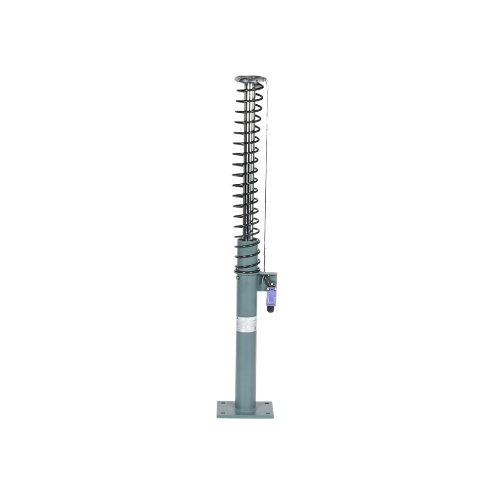
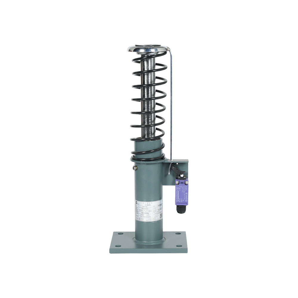
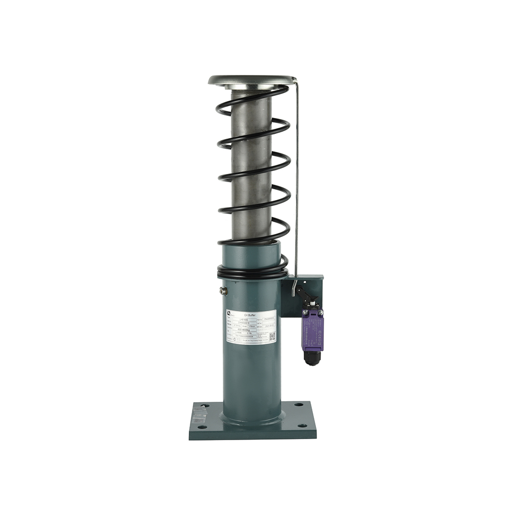
 LHB 160E Oil Buffer Lift Safety PartAn LHB-E series elevator oil buffer; use its test certificate and oil-volume data when screening rated speed, not stroke alone.View Product →
The chart explains why a 100 mm buffer cannot be stretched to a 1.75 m/s project simply by machining a longer plunger. The oil volume displaced during impact is fixed by the kinetic energy of the car and its rated load at 115% of speed, so the stroke has to exist inside the cylinder, not outside it.
If you are checking a specific project against the standard, the elevator oil buffer guide to capacity, stroke and standards walks through the same calculation with worked examples and the buffer test sequence.
What a Custom Order Actually Changes
Customisation on an LHB-E buffer normally touches five points on the drawing: the mounting flange, the plunger top plate, the reset switch, the oil fill grade and the nameplate. None of those alters the certified deceleration curve, provided the orifice is left alone.
- Standard flange and bolt pattern
- Fixed stroke from the six-model range
- Standard reset switch bracket
- Standard oil fill and nameplate
- Project-specific flange and bolt spacing
- Plunger cap matched to the car buffer plate
- Switch type and cable exit chosen by the OEM
- Oil grade recorded against cold-shaft conditions
The line between safe customisation and re-certification is drawn at the orifice. Flange patterns, plunger caps, switch brackets and plate markings are mechanical interfaces: changing them keeps hydraulic behaviour identical and the existing type test stays valid. Changing the orifice diameter, the internal spring rate or the oil viscosity grade changes deceleration, and the buffer becomes a different product that needs its own test.
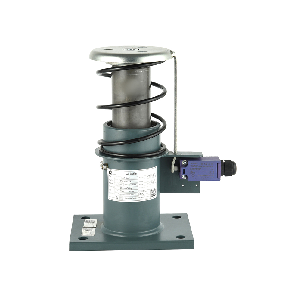
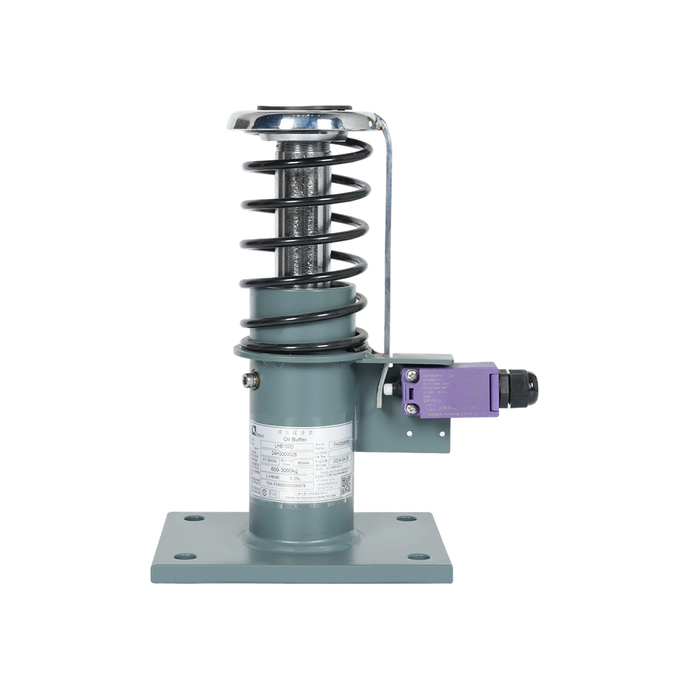
 LHB 200E Hydraulic buffer elevator partLHB 200E hydraulic buffer elevator part features a robust structure and precise engineering to ensure stable and reliable performance under various operating condition...View Product →
Five Documents to Request Before a Purchase Order
A qualified LHB-E supplier can produce five documents on request: the type-test certificate for the exact model, a dimensional drawing with tolerances, the material certificate for the pressure cylinder, the oil specification, and a neutral salt-spray report.
- Type-test certificate naming the model, stroke, test mass and impact speed used during certification.
- Dimensional drawing showing buffer height, plunger travel, flange bolt circle and base footprint.
- Mill certificate for the pressure cylinder with a heat number traceable to the delivered batch.
- Oil specification stating the viscosity grade and fill volume, signed against the type-test file.
- Salt-spray report to ISO 9227, typically 480 hours for external or shaft-mounted installations.
The cylinder certificate is the one most often missing. A buffer is a pressure vessel in everything but name: wall thickness, material grade and weld quality decide whether it survives a 115% impact without permanent deformation, and a mill certificate tied to the batch is the only way to confirm that after arrival.
Oil, Sealing and the 120-Second Reset
An oil buffer must return to its fully extended position within 120 s of an impact, and that reset is governed by oil viscosity, orifice geometry and spring preload rather than by cylinder size.
LHB-E units run on mineral hydraulic oil, normally in the ISO VG 32 to ISO VG 46 band, with the grade recorded on the type-test file. Topping up with a different viscosity changes the return time, and in cold-shaft installations it can push reset past the 120 s limit. Two checks cover most of the risk: a sight glass that shows the correct level at commissioning, and a written statement of the fill grade in the delivery documents.
Sealing is the second failure mode. Plunger seals on a hydraulic buffer see high pressure over a short stroke, so nitrile compounds are the baseline and low-temperature shafts need a compound rated below minus 20 C. Ask what the seal material is, not whether seals are included. The reset verification switch matters for UCMP-aware designs as well: a mechanical contact must actuate at the fully extended position, or the controller will read a fault after every normal stop.
Lead Time, Minimum Order and the Costs That Hide
Lead time on a custom LHB-E buffer is driven by three steps: cylinder machining, oil filling and type testing. Only the first one moves when you change a flange.
Everything else is fixed setup work, which is why it lands on the quotation as a minimum order quantity or a separate line item. Budget for a 20 to 40 unit minimum once a non-standard flange is introduced, and for a dedicated test fee if the orifice or spring rate changes, because a new buffer has to be tested before it can be sold as a safety component.
- Re-test cost: any change to orifice, spring or oil grade moves the buffer outside its existing certificate.
- Sea freight handling: buffers shipped oil-filled need sealed plunger protection and a declared net mass for lifting.
- Documentation mismatch: a certificate quoting a different model suffix will stall customs clearance and site acceptance.
- Spare parts: order seal kits and reset springs with the first batch, since later single-unit orders carry their own minimum.
Sourcing the Buffer Alongside Its Neighbours
Shanghai Liftech Elevator Accessories Co., Ltd. has manufactured elevator safety components since 2004 and completed its four-line portfolio of safety gear, overspeed governor, hydraulic buffer and rope brake in 2015, which means an LHB-E buffer can be ordered together with the governor and linkage that trigger it.
The company reports annual output value rising from more than RMB 30 million in 2010 to more than RMB 150 million in 2023, and set a 2024 goal of becoming a globally trusted safety-component brand through technical development, lean production and organisational change. For a buyer, the practical value of that breadth is interface compatibility: buffer, governor and safety linkage are designed against the same speed and load assumptions, so the triggering chain does not have to be reconciled across three suppliers.
The LHB-E series oil buffer range lists all six strokes with their drawings, and the D-series sits alongside it for projects that need a different platform.
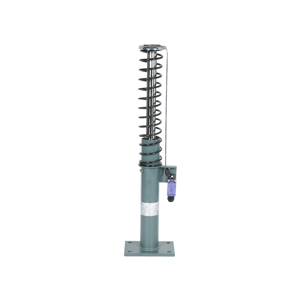
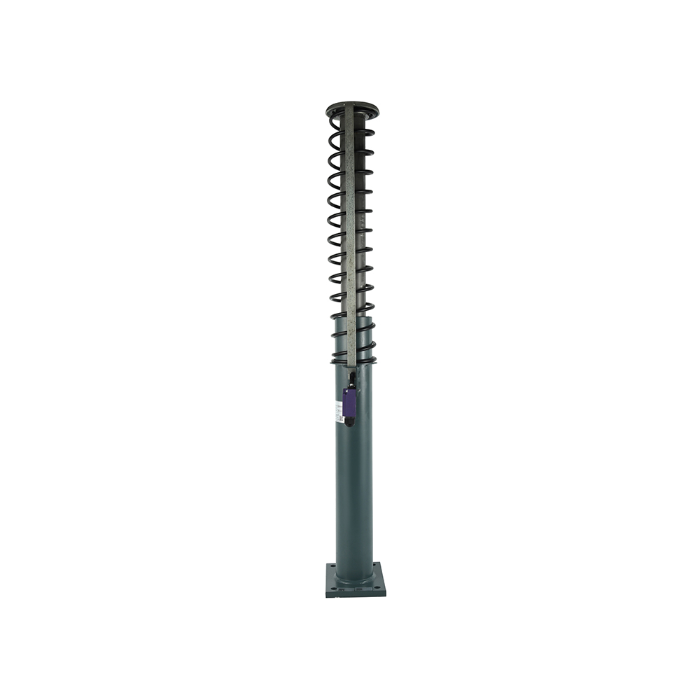 LHB 250E Hydraulic Buffer for Lift ApplicationsA 250 mm nominal-stroke hydraulic buffer in the LHB-E series; the minimum-stroke calculation points to this size for 1.75 m/s projects.View Product →
Questions Buyers Ask Before Signing
What stroke does a 1.75 m/s lift need from an oil buffer?
About 207 mm. Applying 0.0674 multiplied by 1.75 squared gives 0.2065 m, so the LHB-250E at 250 mm nominal stroke is the correct choice from the LHB-E range, while the LHB-200E falls 7 mm short of the minimum-stroke rule. Confirm the final figure against the buffer's own type-test certificate, because test mass can shift the approved range.
Which standards apply to an LHB-E buffer sold into the EU and into China?
EN 81-20:2020 clause 5.8.2 sets the buffer requirements, with testing under EN 81-50, and GB/T 7588.1-2020 covers the Chinese market. Both routes require a type-examination certificate from an accredited body; a supplier self-declaration does not cover a safety component.
How is buffer deceleration verified on delivery?
It is not verified by inspection. The limits of 1 g average deceleration and peaks above 2.5 g lasting no more than 0.04 s are demonstrated during the type test at 115% of rated speed, and the certificate carries the measured curve. Incoming inspection can confirm stroke, dimensions, oil level and switch function only.
Can an LHB-E buffer be repaired on site?
The oil, reset spring and reset switch can be replaced in the field; the cylinder, plunger and orifice cannot. Those three parts define the certified deceleration curve, so substituting any of them turns a certified buffer into an untested one, regardless of how closely the replacement part matches the original.