 English
 中文简体
中文简体 русский
 Español
 Deutsch

How Does an Elevator Over-Speed Governor Work?
Content
- 1 The Role of the Over-Speed Governor in Elevator Safety
- 2 Working Principle and Mechanical Operation
- 3 Types of Elevator Over-Speed Governors
- 4 Governor Rope: Specifications and Tension Requirements
- 5 Safety Gear Integration
- 6 Inspection, Testing, and Maintenance Standards
- 7 Procurement Guide for B2B Buyers
- 8 FAQ
- 9 References
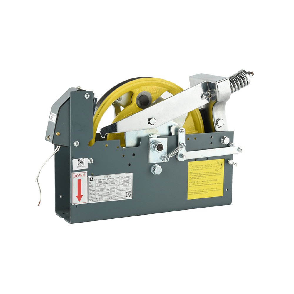
An elevator over-speed governor is a mechanical safety device that monitors car velocity in real time and initiates emergency braking when the descending or ascending speed exceeds a defined threshold. It is one of the most critical components in the elevator safety chain. Without a functioning governor, the safety gear system has no trigger mechanism, and runaway car scenarios cannot be arrested mechanically. This guide covers the working principle, component specifications, safety gear integration, and procurement requirements for engineers and B2B buyers.
The Role of the Over-Speed Governor in Elevator Safety
Position in the Safety Chain
The elevator safety system operates as a layered chain of independent protection mechanisms. The elevator over-speed governor sits at the detection layer. It monitors car speed through a governor rope connected to a pulley driven by the car's movement. When speed exceeds the trip threshold, the governor mechanically arrests the rope, which pulls the safety gear linkage and clamps the guide rails to stop the car.
- Layer 1: Normal operation speed control via the drive system
- Layer 2: Electrical overspeed detection via encoder or tachometer
- Layer 3: Over-speed governor mechanical trip (first trigger)
- Layer 4: Safety gear clamping on guide rails (final arrest)
- Layer 5: Buffers at the pit level for residual energy absorption
Trigger Speed Thresholds
International standards define the governor trip speed relative to the rated car speed. EN 81-20 and ASME A17.1 both specify that the governor must trip before the car reaches 115% of its rated speed for the first electrical contact, and before 125% for the mechanical rope arrest that activates the safety gear.
- Electrical switch trip: at or before 115% of rated speed
- Mechanical rope arrest: at or before 125% of rated speed
- Example: rated speed 1.6 m/s, electrical trip at 1.84 m/s, mechanical trip at 2.0 m/s
- Minimum trip speed for safety gear activation: 0.8 m/s per EN 81-20 clause 5.6.2
Working Principle and Mechanical Operation
Centrifugal Flyweight Mechanism
The core of the elevator overspeed governor working principle is a centrifugal flyweight assembly mounted on a rotating sheave. As the governor rope drives the sheave, the flyweights rotate outward due to centrifugal force. At normal operating speeds, a calibrated spring holds the flyweights within their rest position. When speed exceeds the trip threshold, centrifugal force overcomes spring tension and the flyweights extend outward far enough to engage a mechanical latch or pawl.
- Flyweight material: cast iron or steel, precision balanced in pairs
- Spring calibration: factory-set and sealed, not field-adjustable
- Sheave diameter: typically 200 mm to 400 mm, depending on rope diameter and trip speed
- Rope groove profile: semicircular with undercut to maximise rope grip at trip
Rope Gripping and Safety Gear Activation
When the flyweights trip the latch, a jaw or wedge mechanism clamps onto the governor rope and arrests its movement. The car continues to move downward momentarily, creating tension in the rope. This tension pulls the safety gear lever linkage upward, driving the safety wedges or rollers into contact with the guide rails. The resulting friction force decelerates the car to a stop.
- Rope arrest force must be sufficient to actuate the safety gear under full load.
- Minimum pull force on safety gear linkage: defined by car mass and safety gear type
- Governor reset: manual reset required after any trip event before resuming service
Types of Elevator Over-Speed Governors
Governors are classified by their direction of protection and by their mechanical configuration. The selection of the overnor type depends on the elevator's rated speed, travel direction risk profile, and applicable standard. The table below compares the main types used in commercial and high-rise installations.
| Type | Direction of Protection | Typical Application | Standard Reference |
|---|---|---|---|
| Unidirectional governor | Downward only | Low to mid-rise, rated speed up to 1.75 m/s | EN 81-20, ASME A17.1 |
| Bidirectional governor | Upward and downward | High-rise, MRL, traction elevators above 1.75 m/s | EN 81-20 clause 5.6.2.1.2 |
| Electronic governor | Both directions via the encoder | High-speed elevators above 6 m/s | EN 81-20, ISO 22559 |
| Combined governor-safety gear unit | Downward (integrated) | Hydraulic elevators, low-rise platforms | EN 81-20, EN 81-41 |
Unidirectional vs Bidirectional Governors
The bidirectional elevator overspeed governor for high-rise buildings is now required in many jurisdictions for traction elevators where counterweight runaway in the upward direction poses a safety risk. EN 81-20:2014 mandates upward overspeed protection for all new traction elevator installations. Unidirectional governors remain acceptable for hydraulic elevators where upward runaway is not a credible failure mode.
Governor Rope: Specifications and Tension Requirements
Rope Diameter and Material Standards
The elevator overspeed governor rope tension requirements are directly related to the force needed to actuate the safety gear. The governor rope must maintain sufficient tension under all operating conditions, including temperature variation and rope stretch over time.
- Standard rope diameter: 6 mm to 10 mm for most commercial elevators
- Construction: 8x19 or 6x19 wire rope, independent wire rope core (IWRC)
- Minimum breaking force: must exceed 8x the maximum force required to actuate safety gear
- Rope tension: maintained by a tensioning pulley in the pit with dea fined minimum weight
- Tension pulley weight: typically 15–25 kg, depending on rope length and diameter
- Replacement interval: when wire breakage exceeds limits per ISO 4344 or ASME A17.1
Safety Gear Integration
Progressive vs Instantaneous Safety Gear
The elevator overspeed governor and safety gear connection determines the deceleration profile experienced by passengers during an emergency stop. The type of safety gear must be matched to the governor trip speed and the rated load of the car. The two main safety gear types differ significantly in their stopping distance and deceleration forces.
| Feature | Progressive Safety Gear | Instantaneous Safety Gear |
|---|---|---|
| Deceleration profile | Gradual, 0.2g to 1.0g | Abrupt, up to 2.5g or higher |
| Stopping distance | Longer, depending on load and speed | Very short, typically under 50 mm |
| Applicable rated speed | Above 1.0 m/s (EN 81-20 requirement) | Up to 1.0 m/s only |
| Guide rail damage | Minimal with proper adjustment | Higher surface wear on rails |
| Reset procedure | Requires upward car movement to release | Manual release by the technician |
| Typical use | Passenger elevators, all speeds above 1 m/s | Service lifts, low-speed freight |
Inspection, Testing, and Maintenance Standards
Annual Testing Protocol
The elevator overspeed governor inspection and maintenance standards require periodic testing to verify trip speed accuracy and mechanical integrity. EN 81-20 and ASME A17.1 both mandate full governor trip tests at defined intervals, typically annually for passenger elevators.
- Visual inspection: check rope condition, tension pulley alignment, and flyweight pivot wear
- Trip speed test: verify governor trips within the specified speed range using a calibrated tachometer
- Rope tension check: confirm the tensioning pulley moves freely, and the rope has no broken wires.
- Safety gear actuation test: confirm safety gear engages and holdsthe car under the rated load
- Reset function test: verify governor resets correctly after manual release
Key Parameters to Verify
- Trip speed: within ±5% of factory-set value
- Rope diameter reduction: replace if worn below 90% of nominal diameter
- Flyweight pivot clearance: replace if lateral play exceeds 0.3 mm
- Spring fatigue: replace the spring assembly at manufacturer-recommended intervals
- Rope lubrication: Apply manufacturer-specified lubricant at 12-month intervals
Procurement Guide for B2B Buyers
Certification Requirements by Market
Buyers sourcing elevator over-speed governor components for international projects must verify that the units carry certifications valid in the destination market. Certification requirements differ between regions and building codes.
- Europe: CE marking under Machinery Directive 2006/42/EC, EN 81-20 type examination
- United States: ASME A17.1 compliance, state-level third-party inspection acceptance
- China: GB 7588-2003 (superseded by GB/T 7588.1-2020), CNCA certification
- Middle East: Gulf Elevator and Escalator Code, often EN 81-20 equivalent
- India: IS 14665 series, BIS certification for key safety components
Technical Specification Checklist
The following parameters must be confirmed in writing before placing bulk orders for elevator safety components.
- Rated car speed compatibility: confirm governor trip speed matches installation requirements
- Direction of protection: unidirectional or bidirectional, as required by local code
- Rope diameter: confirm compatibility with existing rope and tensioning system
- Safety gear type compatibility: progressive or instantaneous, confirm pull force rating.
- Sheave diameter and groove profile: verify dimensional drawings against installation space
- Material certification: Request mill certificates for all structural steel components
- Type examination certificate: confirm the issuing notified body is accepted by the local authority
FAQ
What is the difference between an overspeed governor and a safety gear?
An elevator overspeed governor is the detection and triggering device. It monitors speed and initiates action when the threshold is exceeded. The safety gear is the arresting device. It clamps onto the guide rails to physically stop the car. The two components work together: the governor detects the overspeed condition and pulls the safety gear linkage, and the safety gear converts that pull force into clamping force on the rails. Neither component functions as a complete safety system without the other.
How often should an elevator overspeed governor be tested?
Per EN 81-20 and ASME A17.1, a full governor trip test with safety gear actuation must be performed at intervals specified by the authority having jurisdiction, typically every one to five years, depending on elevator type and usage intensity. Annual visual inspections and rope condition checks are required in most jurisdictions regardless of the full test interval. The elevator overspeed governor inspection and maintenance standards in each market define the exact schedule and documentation requirements.
When is a bidirectional governor required?
A bidirectional elevator overspeed governor for high-rise buildings is required by EN 81-20:2014 for all new traction elevator installations where the counterweight is not protected by its own safety gear. In this configuration, an upward runaway of the car caused by counterweight imbalance or drive failure must be arrested by the car-mounted safety system acting in both directions. Existing installations with unidirectional governors may be subject to retrofit requirements during major modernisation projects, depending on local regulations.
References
- European Committee for Standardisation. (2014). EN 81-20: Safety Rules for the Construction and Installation of Lifts – Lifts for the Transport of Persons and Goods. CEN.
- American Society of Mechanical Engineers. (2022). ASME A17.1/CSA B44: Safety Code for Elevators and Escalators. ASME.
- International Organisation for Standardisation. (2004). ISO 4344: Steel Wire Ropes for Lifts – Minimum Requirements. ISO.
- Barney, G., & Lorente, M. (2001). Elevator Traffic Handbook: Theory and Practice. Spon Press.
- Strakosch, G. R., & Caporale, R. S. (2010). The Vertical Transportation Handbook (4th ed.). Wiley.
- State Administration for Market Regulation, China. (2020). GB/T 7588.1-2020: Safety Rules for the Construction and Installation of Lifts. Standards Press of China.


