 English
 中文简体
中文简体 русский
 Español
 Deutsch

Why a Precision Overspeed Governor Is Essential for Elevator Passenger Safety ?
Content
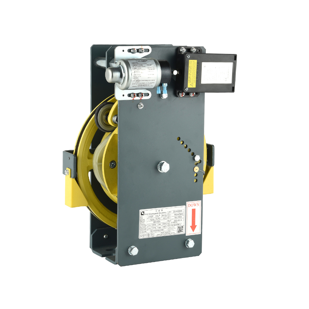
The precision overspeed governor serves as the final mechanical safeguard against catastrophic elevator failures. This device continuously monitors car velocity and triggers emergency braking when predetermined speed thresholds are exceeded. For facility managers and elevator contractors, understanding the elevator overspeed governor working principle ensures proper specification, installation, and compliance with international safety standards.
Understanding the Core Function of Speed Monitoring
Modern vertical transportation systems rely on multiple safety layers. The governor represents the last line of defense when primary braking systems fail.
The Critical Role in Vertical Transportation Safety
Elevator systems face risks from hoisting rope failure, control system malfunction, or drive mechanism breakdown. The precision overspeed governor operates completely independently of electrical control systems. This mechanical independence ensures protection continues even during total power failures or electrical faults. The device monitors both ascending and descending movements, addressing the dangerous scenario where a counterweight might drag an empty car upward at excessive velocity.
Regulatory Framework and Compliance Standards
EN 81-20:2014 and EN 81-50:2014 establish mandatory requirements for governor design and testing in European markets. These standards specify that governors must activate safety gears when the car speed reaches 115% of the rated velocity. The electrical switch must trip earlier, typically at 110% of rated speed, ensuring power cutoff precedes mechanical braking. ASME A17.1 provides equivalent requirements for North American installations. Compliance documentation must trace component testing back to certified laboratories.
The Working Principle of Centrifugal Systems
The centrifugal overspeed governor mechanism dominates commercial applications due to its reliability and fail-safe characteristics.
Flyweight Mechanism and Centrifugal Force Detection
Inside the governor housing, a pair of flyweights attaches to a rotating spindle driven by the governor sheave. Spring tension holds these weights in a retracted position during normal operation. As rotational speed increases, centrifugal force acts upon the flyweights. When velocity exceeds the calibrated threshold, the outward force overcomes spring resistance. The flyweights swing outward and contact a trip mechanism. This mechanical action requires no external power source, functioning purely through physical principles.
Two-Stage Protection: Electrical and Mechanical
The governor provides sequential protection through two distinct stages. First, an electrical switch opens when speed reaches approximately 110% ofthe rated velocity. This action cuts power to the hoisting motor and activates the motor brake. If the car continues accelerating despite electrical braking, the mechanical stage engages at 115% of the rated speed. The governor locks the rope, pulling the safety gear linkage and forcing brake shoes against guide rails.
The following table compares these two protection stages:
| Protection Stage | Activation Speed | Primary Action | Reset Method |
| Electrical Switch | 110% of rated speed | Cuts motor power, applies motor brake | Automatic reset |
| Mechanical Trip | 115% of rated speed | Locks the governor rope, activates the safety gear | Manual reset required |
| Response Time | 10-50 milliseconds | Immediate power interruption | Technician verification needed |
| Fail-Safe Nature | Independent of power supply | Centrifugal force activation | Spring-return mechanism |
Types of Overspeed Governors
Different building requirements and elevator configurations demand specific governor designs.
Monodirectional vs Bidirectional Designs
Monodirectional governors detect overspeed conditions in the downward direction only. These units suffice for standard traction elevators where upward overspeed risks are minimal. Bidirectional governors monitor both directions, providing essential protection for high-rise installations and hydraulic systems where counterweight imbalances might cause upward acceleration. Bidirectional units contain additional linkages and reversing mechanisms, increasing complexity but ensuring comprehensive protection.
Centrifugal vs Inertia Mechanisms
While the centrifugal overspeed governor mechanism dominates the market, inertia-type governors serve specific applications. Inertia governors use flyweight displacement rather than centrifugal swing to detect acceleration. These units offer different response characteristics suitable for certain hydraulic elevator configurations. However, centrifugal designs provide more consistent calibration and wider industry acceptance.
The comparison below outlines key distinctions between governor types:
| Governor Type | Detection Method | Directional Capability | Typical Application | Maintenance Frequency |
| Centrifugal Monodirectional | Flyweight swing | Downward only | Standard traction elevators | Quarterly inspection |
| Centrifugal Bidirectional | Flyweight swing | Upward and downward | High-speed/high-rise systems | Monthly inspection |
| Inertia Type | Weight displacement | Varies by design | Hydraulic elevators | Quarterly inspection |
| Electronic-Assisted | Encoder feedback | Programmable | Modern MRL elevators | Bi-annual calibration |
Technical Specifications and Calibration
Proper specification requires understanding critical engineering parameters.
Trip Speed Calculations and Tolerance Ranges
The EN 81-20 overspeed governor requirements mandate precise calibration. The tripping speed must not exceed 115% of the rated elevator velocity under any circumstances. Manufacturers calibrate units using standardized test benches measuring rotational speed against flyweight displacement. Tolerance ranges typically stay within ±2% of setpoint values. High-speed elevators demand governors with faster response times, often requiring specialized materials to withstand increased dynamic loads.
Rope Tension and Sheave Diameter Ratios
The governor rope connects the sheave to the tensioning device in the pit. EN 81-20 specifies that the ratio between sheave diameter and rope diameter must equal or exceed 30:1. This ratio prevents excessive bending stress that could cause premature rope failure. Tensioning pulleys maintain consistent rope tension throughout the travel distance, ensuring accurate speed transmission from car movement to governor rotation.
Response Time Requirements
High-speed elevators require governors responding within 30-50 milliseconds. Standard elevators tolerate response times up to 200 milliseconds. The elevator safety gear activation system must complete full engagement within specified timeframes to prevent dangerous acceleration before braking takes effect.
Installation and Maintenance Protocols
Long-term reliability depends on proper installation and systematic maintenance.
Alignment and Tensioning Procedures
Installation requires precise alignment between the governor sheave and the traction machine. Misalignment causes rope wear and erratic speed detection. Rope tension must match manufacturer specifications, typically maintained by tensioning weights in the pit. The tensioning pulley requires sufficient travel range to accommodate rope stretch over the installation lifetime.
Periodic Testing Requirements
Regulations mandate annual operational testing for all mechanical vs electronic overspeed governor systems. Testing involves simulating overspeed conditions to verify both the electrical switch function and the mechanical trip action. Technicians use specialized tools to manually trip the governor during controlled test runs. Safety gear engagement tests occur less frequently but remain mandatory for certification compliance.
Troubleshooting Common Issues
Common problems include rope elongation requiring tension adjustment, flyweight wear affecting calibration accuracy, and pulley groove contamination causing slip. Regular inspection should examine:
- Governor rope condition for fraying or corrosion
- Flyweight pivot points for lubrication and wear
- Electrical switch contact integrity
- Sheave groove profile for excessive wear
- Tensioning device freedom of movement
FAQ
What is the difference between mechanical and electronic overspeed governors?
Mechanical governors rely on centrifugal force and physical linkages, operating independently of electrical systems. Electronic governors use encoders and programmable logic for speed monitoring. While electronic systems offer data logging and adjustable parameters, mechanical governors provide fail-safe operation during power failures. Most modern installations use mechanical governors as primary protection with electronic monitoring as secondary verification.
How often must an elevator overspeed governor be tested and certified?
Annual testing is mandatory under EN 81-20 and ASME A17.1 standards. High-speed elevators require monthly inspections of governor ropes and tensioning devices. Complete safety gear engagement tests occur every 2-5 years, depending on local jurisdiction requirements. All testing must be documented and performed by certified elevator technicians.
Can an existing elevator be retrofitted with a bidirectional governor?
Retrofitting requiresan engineering assessment of the existing safety gear system. Bidirectional governors demand compatible safety gears capable of braking in both directions. The retrofit process involves replacing the governor unit, upgrading safety gear jaws, and potentially modifying the tensioning system. Cost-benefit analysis should compare retrofit expenses against full system replacement, particularly for elevators approaching end-of-service life.
References
- Shanghai Liftech Elevator Accessories Co., Ltd. (2025). How Reliable Is Your Precision Overspeed Governor? Technical Documentation and Safety Analysis.
- A-FLY Elevator & Escalator Parts Supplier. (2025). What Is the Function of an Elevator Overspeed Governor? How Does It Protect Passenger Safety? Vertical Transportation Safety Review.
- Acute New Elevators. (2026). A Clear Guide to EN 81-20 and EN 81-50 Lift Standards. UK Elevator Safety Compliance Documentation.
- Elevator World. (2025). Elevator Safety Components: Governors and Mechanical Brakes. Industry Technical Journal.
- Dazen Elevator Technology. (2025). Elevator Overspeed Governor: All You Need to Know. Engineering Technical Guide.
- KONE Corporation. Elevator Standards EN 81-20 and EN 81-50: Technical Fact Sheet. European Lift Safety Standards Documentation.


