
 English
 中文简体
中文简体 русский
 Español
 Deutsch


Custom Elevator Oil Buffer Sizing: Stroke, Speed, and Deceleration Explained
Content
- 1 What a Custom Elevator Oil Buffer Actually Is
- 2 The Three Inputs That Size a Custom Oil Buffer
- 3 Catalogue Buffer vs Custom Oil Buffer: Where the Difference Shows
- 4 Deceleration Limits and Orifice Design: What a Test Report Must Show
- 5 A Sourcing Checklist for a Custom Oil Buffer Order
- 6 FAQ: Custom Elevator Oil Buffers
An oil buffer that passed type approval at 1.0 m/s with a 1,000 kg gross load can still log a peak deceleration above 2.5 g once it is fitted to a 1.6 m/s machine in a real shaft. That gap between the test bench and the installation is where the market for a custom elevator oil buffer lives. Villa lifts with shallow pits, freight elevators re-rated during modernization and industrial lifts whose gross mass sits between two catalogue steps all fall outside the fixed stroke and capacity grid.
Sizing one is a calculation, not a catalogue lookup. Three inputs decide nearly everything, and the order in which they are fixed matters as much as the numbers themselves.
What a Custom Elevator Oil Buffer Actually Is
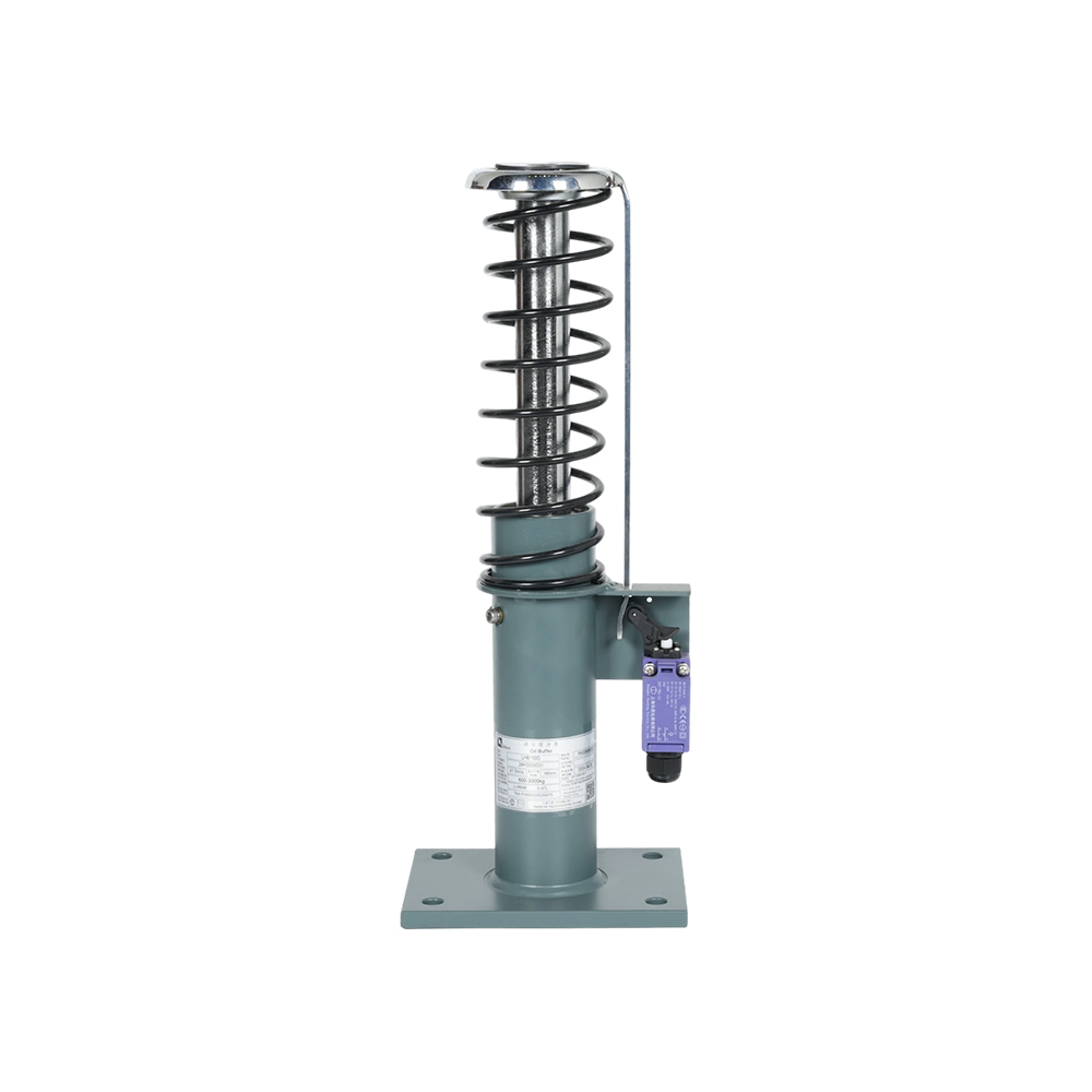
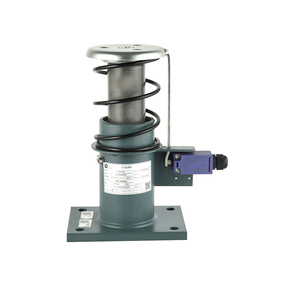
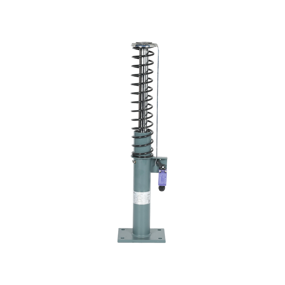
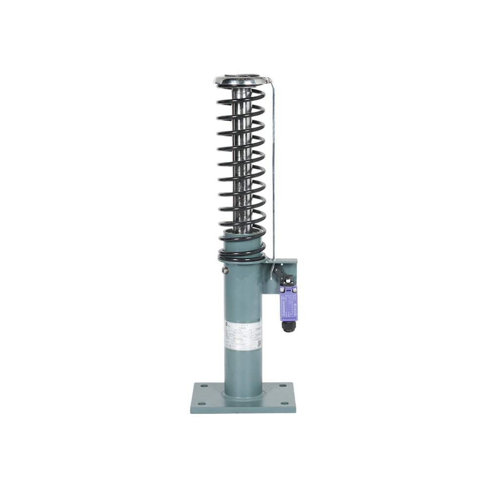
A custom elevator oil buffer is a hydraulic energy-dissipation buffer built to a specified rated speed, gross system mass, available stroke and mounting interface, rather than selected from a fixed list of standard models.
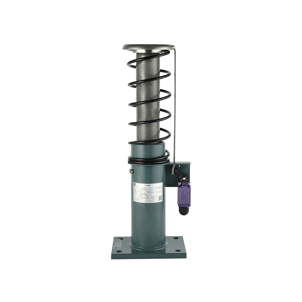
Mechanically the device is simple. A striking plate drives the plunger down, oil is forced through a metering orifice, and the oil absorbs the kinetic energy of the car or counterweight as heat. What separates a competent custom buffer from a generic one is the orifice profile. The metering rod is tapered so that the open area changes along the stroke, holding deceleration roughly flat instead of letting it spike in the first millimetre of travel.
Oil buffer: a hydraulic buffer in which the plunger drives oil through a metering orifice; the orifice geometry is shaped along the stroke so that deceleration stays inside the standard envelope, and the oil dissipates the kinetic energy as heat.
Type approval is family approval, not a promise about every combination. A certificate issued for one speed and mass pair says nothing about another, and the further a project drifts from the tested points, the further the deceleration curve moves. Shanghai Liftech Elevator Accessories Co., Ltd. (Liftech), founded in 2004 by an engineering team from the elevator industry, builds oil buffers in two families, LHB-D and LHB-E, alongside safety gears, overspeed governors and rope brakes.
The Three Inputs That Size a Custom Oil Buffer
Rated speed, gross mass P+Q and available pit depth together fix the stroke, the bore and the oil volume of a custom oil buffer.
Rated speed enters through a fixed rule. Standards size the buffer against 115% of rated speed, and the baseline stroke comes from the gravity stopping distance at that speed: s = 0.0675 v squared, in metres. The relationship is quadratic, which is why the figures below do not grow the way most buyers expect.
At 0.63 m/s the baseline is 27 mm. At 2.5 m/s it is 422 mm, almost sixteen times more. Pit depth is normally the binding constraint, and it decides whether the project buys a longer buffer or a reduced-stroke design that has to meter harder.
Mass does not change the required stroke, but it changes everything else. A heavier car at the same speed carries more kinetic energy into the buffer, so bore, plunger area and oil volume have to grow to keep deceleration inside the limit. Two buffers with an identical 175 mm stroke can therefore be entirely different parts. For a capacity and stroke reference across standard ratings, an elevator oil buffer guide covering capacity, stroke and standards is worth reading before a specification is frozen.
| Parameter | Typical input | Effect on the buffer |
|---|---|---|
| Rated speed | 0.5 to 2.5 m/s | Sets the baseline stroke and the impact speed used in testing |
| Gross mass P+Q | 800 to 4,000 kg | Sets bore, plunger area and oil volume |
| Free pit depth | 250 to 1,200 mm | Caps the stroke and may force a reduced-stroke design |
| Mounting interface | Base plate pattern, plunger cap | Decides whether the unit drops into the existing pit |
| Oil specification | Mineral hydraulic oil, stated viscosity | Controls damping consistency across the temperature range |
| Certification route | EN 81-20, GB 7588 or ASME A17.1 | Determines the test evidence supplied with the unit |
Catalogue Buffer vs Custom Oil Buffer: Where the Difference Shows
A standard catalogue buffer wins on price and lead time; a custom oil buffer wins the moment one sizing input falls outside the standard grid.
- Stroke offered only in fixed steps, typically 100 mm, 175 mm and 250 mm
- Capacity matched to a published band rather than your measured P+Q
- Lead time measured in days from stock
- Generic type certificate supplied with the unit
- Fits new-build lifts at standard speeds and standard pit depths
- Stroke built to the free pit depth you actually have
- Bore and oil volume matched to the verified gross mass
- Lead time measured in weeks, including test documentation
- Model-specific deceleration-versus-stroke curve
- Fits retrofits, freight lifts, villa lifts and industrial installations
Liftech's LHB-D range runs from the LHB100D up to the LHB250D, and the LHB-E family covers the same span from the LHB-100E upwards. Both arrive as a complete assembly with cylinder, plunger, oil specification and mounting plate. The full oil buffer range sits alongside the company's safety gear and governor lines, so a single supplier can cover the whole safety chain.
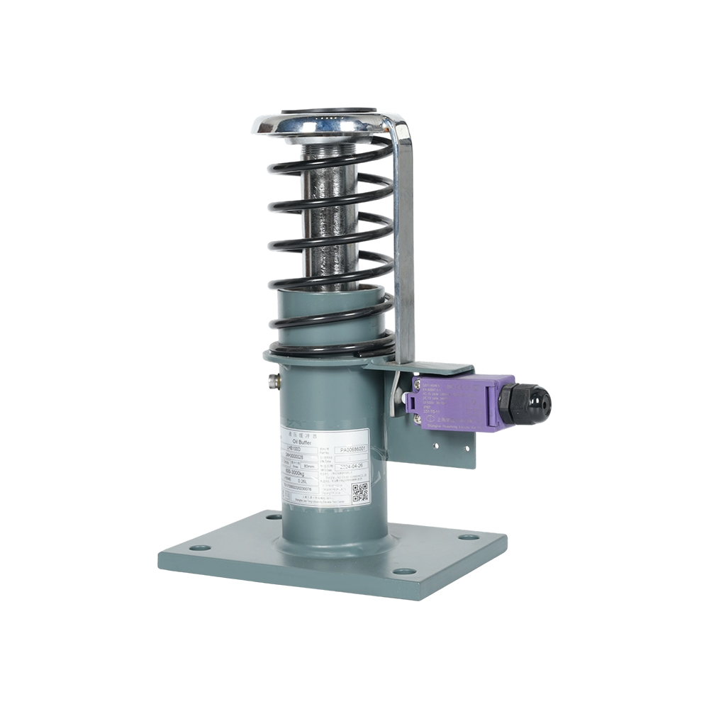 LHB100D Hydraulic Oil Buffer for Elevator SafetyThe LHB100D is a compact LHB-D series oil buffer using spring and hydraulic damping for low-speed elevators and retrofit projects.View Product →
 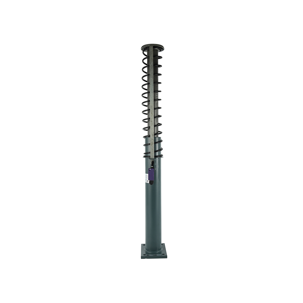 LHB 250E Hydraulic Buffer for Elevator and Lift SystemsA hydraulic LHB-E series buffer that uses damping to reduce impact, vibration, and noise across construction hoist, residential, and commercial elevator applications.View Product →
Deceleration Limits and Orifice Design: What a Test Report Must Show
A custom oil buffer is compliant only when average deceleration stays at or below 1 g and no point in the stroke exceeds 2.5 g, the limits set by EN 81-20 and mirrored in GB 7588.
The two limits do different jobs. The 1 g average governs how the stopping distance feels to passengers and how much load reaches the car frame. The 2.5 g peak governs the equipment, because a sharp spike is what cracks a buffer base or loosens a guide rail bracket.
The peak is the number that fails in practice. An orifice that opens too slowly at the start of the stroke produces a hard spike in the first few millimetres of travel and then relaxes, delivering a healthy average and a failing peak. A well-shaped metering rod keeps the curve between roughly 0.5 g and 1 g across the middle of the stroke.
Ask for the deceleration-versus-stroke curve. A single average figure hides the peak that decides whether the buffer passes.
A Sourcing Checklist for a Custom Oil Buffer Order
Five checks decide whether a custom oil buffer arrives as a drop-in assembly or as a return shipment.
- Confirm the impact speed. Use 115% of rated speed, not the nameplate figure, so a 1.6 m/s lift is calculated and tested at 1.84 m/s.
- Send the real gross mass. P plus Q, including the actual car finish and the rated load, not a rounded nominal figure.
- Measure the pit. Free depth under car and counterweight, base plate position and clearance around the plunger cap.
- Match the mounting interface. Bolt pattern, striker plate diameter and plunger cap profile decide whether the unit bolts straight in.
- Require model-specific deceleration data. A generic certificate is not evidence for your speed and mass combination.
For mid-to-high capacity slots in the LHB-D family, models such as the LHB200D cover gross masses that a stock 175 mm unit cannot.
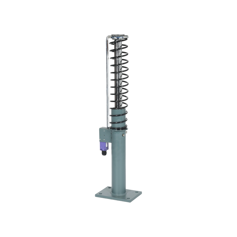 LHB200D Hydraulic Oil Buffer for Elevator Safety SystemsMid-to-high capacity LHB-D series buffer with hydraulic damping, smooth deceleration without spring rebound, and compact low-maintenance construction for elevator installations.View Product →
One further factor deserves a line in the purchase order: oil specification and the temperature range the shaft will see. Viscosity drift changes the damping curve over the life of the buffer, and cold plant rooms are the usual reason a unit behaves well on the test bench and poorly in January.
FAQ: Custom Elevator Oil Buffers
What is a custom elevator oil buffer?
It is a hydraulic buffer manufactured to a specific rated speed, gross mass, stroke and mounting interface instead of being chosen from a fixed catalogue grid. The orifice profile is matched to those inputs so the deceleration curve stays inside the standard envelope at the tested impact speed.
When is a custom oil buffer better than a standard model?
Whenever a sizing input falls between catalogue steps: a pit too shallow for the standard stroke, a gross mass heavier than the stock capacity band, a re-rated speed after modernization, or a mounting interface that no stock unit matches.
What information should I send with an oil buffer inquiry?
Send rated speed, gross mass P+Q, free pit depth, base plate bolt pattern, plunger cap diameter, oil type already in use and the certification route you need. Suppliers who receive those seven items can quote a workable unit without a second round of questions.
How do I verify deceleration performance before installation?
Request the deceleration-versus-stroke curve for the exact model and speed, not an average figure and not a family certificate. The curve should stay below 2.5 g at every point and average 1 g or less over the full stroke.
The buffer is the last mechanical barrier between a car and the pit floor, and it only does its job once, at the worst possible moment. Ordering against real numbers costs a few days of engineering time. Guessing costs a deceleration curve that never had a chance.