
 English
 中文简体
 русский
 Español
 Deutsch



Elevator Safety Gear Linkage Mechanism: Stroke, Synchronization and Reset
Content
- 1 What the Linkage Mechanism Does in the Safety Chain
- 2 Anatomy of a Linkage Assembly
- 3 From Governor Rope to Wedge: The Trip Sequence
- 4 Speed, Stroke and Synchronization: The Numbers That Decide
- 5 Configuring the Linkage for Different Elevator Types
- 6 Inspection and Reset in the Field
- 7 Practical Questions Engineers Ask
A progressive safety gear has to hold car deceleration between 0.2 g and 1.0 g, the band fixed by EN 81-20:2014 clause 5.6.2.3.2. That band is only reachable when both wedges touch the guide rails within the same instant. The elevator safety gear linkage mechanism is the only component in the chain that can guarantee that timing, and it is also the part most often left misadjusted after installation.
One pull, two wedges, one instant. Every adjustment on the linkage exists to protect that equality.
What the Linkage Mechanism Does in the Safety Chain
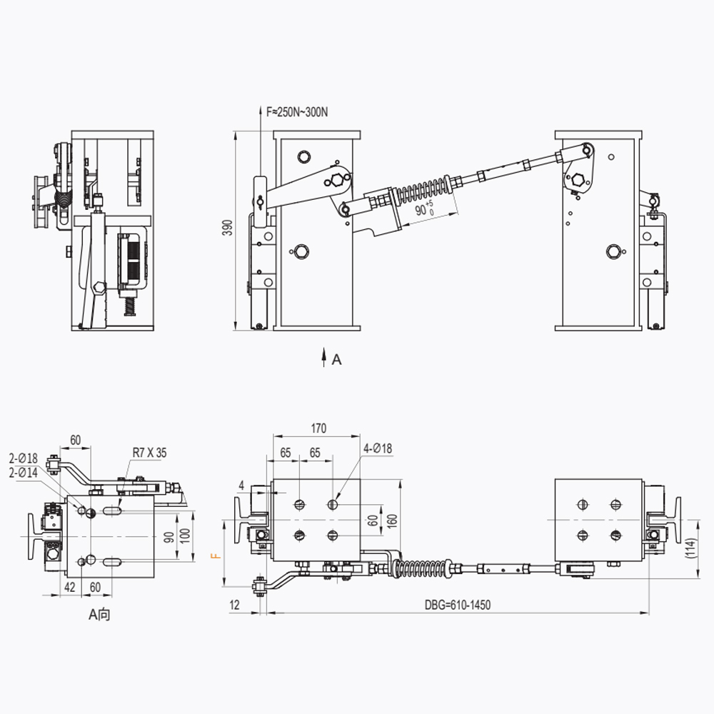
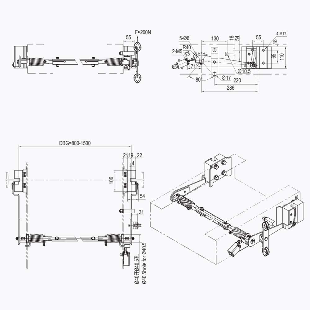
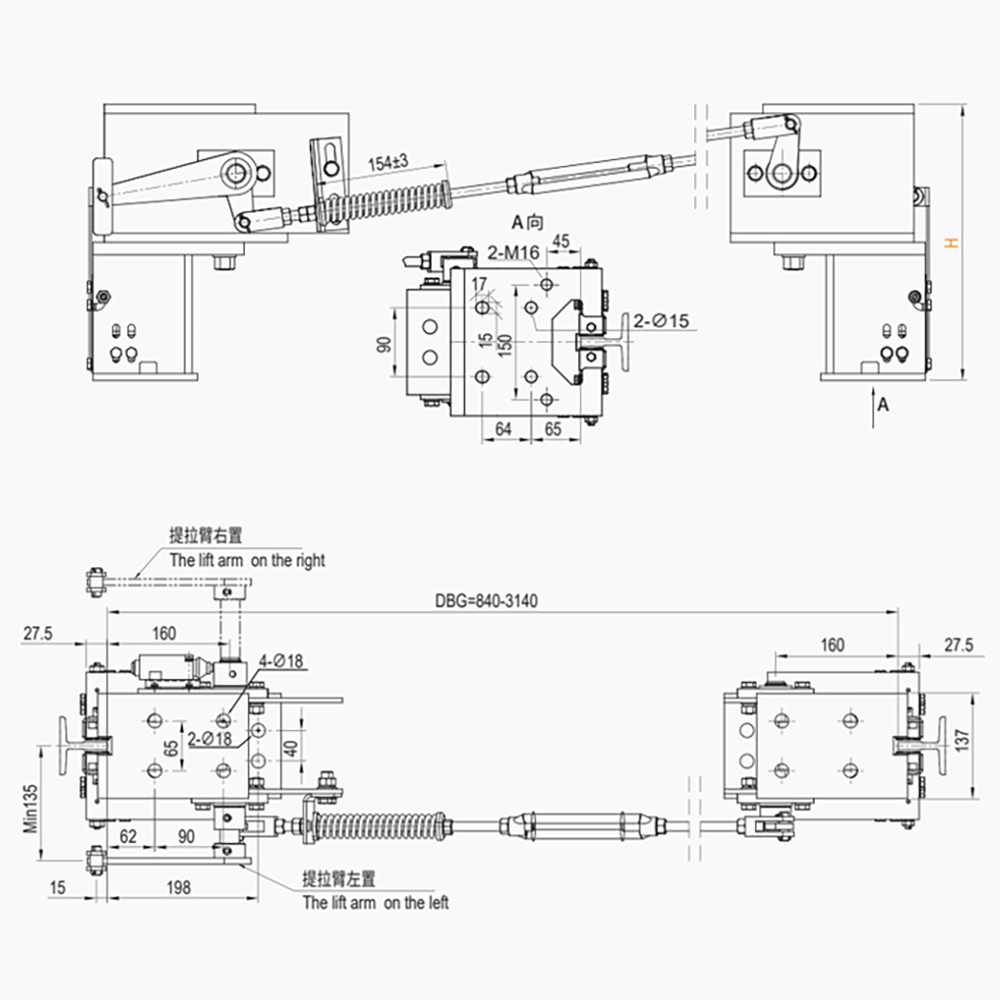
The elevator safety gear linkage mechanism is the mechanical train that converts the governor rope's pull into a synchronized lift of both safety gear wedges on the car frame.
It sits between two devices that are already well understood. The overspeed governor detects speed. The safety gear clamps the rails. Neither one works alone: a governor that trips perfectly still produces nothing if the force never reaches the lifting rods, and a safety gear that is correctly rated still stops the car on one rail if only one wedge rises.
Definition: the safety gear linkage mechanism is the rod, lever and spring assembly that transmits the governor's tripping force to both safety gear lifting points, keeps those two points in step, and returns the wedges to the released position after a manual reset.
Two quantities govern every design decision in that assembly. The linkage must transmit enough force to lift the wedges against their return springs and against guide rail friction. It must also deliver enough stroke to move each wedge from its rest position to full contact and hold it there while the car decelerates.
Where installations go wrong is treating the linkage as a fixed accessory rather than an adjustable transmission. A linkage that is 5 mm out of adjustment does not reduce braking by 5 mm. It changes which rail does the work, and the deceleration curve follows.
The linkage does not brake the car. It decides whether the braking is symmetrical, and symmetry is what keeps deceleration inside the 0.2 g to 1.0 g window.
Anatomy of a Linkage Assembly
A linkage assembly carries six working parts plus one electrical interlock, and each of them has a characteristic wear pattern that a maintenance engineer can read directly.
| Component | Function in the chain | Where it fails first |
| Governor rope grip | Locks onto the governor rope when the governor trips and starts the pull | Slippage on an oily or elongated rope |
| Main pull rod | Carries the tripping force from the rope grip down to the car frame | Bending after a trip under full load |
| Equalizing lever | Splits one pull into two equal pulls for the left and right sides | Seized pivot pin, uneven force split |
| Side pull rods | Transmit force from the beam to each safety gear housing | Threaded ends knocked out of adjustment |
| Lifting rods | Raise the wedges into contact with the guide rails | Lost stroke through worn pins |
| Return springs | Release the wedges after reset and keep the linkage free of slack | Fatigue and permanent set |
| Electrical safety contact | Confirms the linkage is in the untripped position before the car may run | Roller gap adjusted too tight or too loose |
Wear matters because the linkage is a stroke budget, not a rigid bar. Every pin clearance, every bent rod and every spring with permanent set consumes travel that should have gone into lifting the wedge. The budget is set at commissioning and it only shrinks from there.
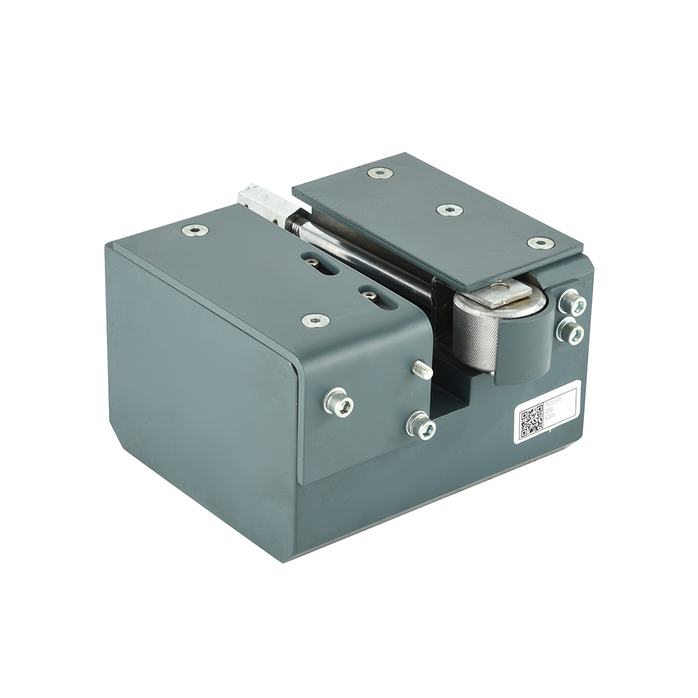
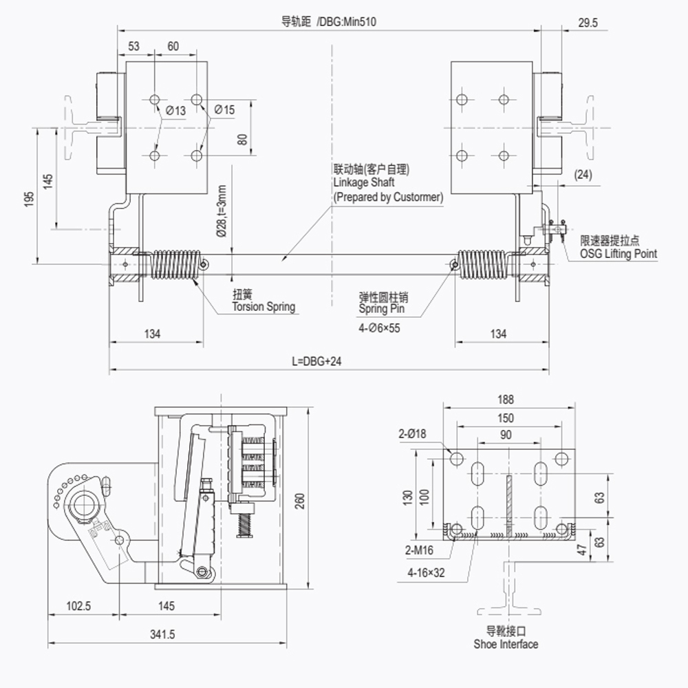 LSD01 Linkage Device for Elevator Safety GearA linkage component for elevator safety gear applications; useful when assessing how pin clearance and linkage wear consume wedge lift.View Product →
A joint with 1 mm of visible clearance costs roughly 1 mm of wedge lift at the rail. Spread that across four joints and the safety gear never reaches the clamping force it was type-tested at.
From Governor Rope to Wedge: The Trip Sequence
Tripping runs through six stages, and the linkage owns stages three to six.
- The governor reaches its tripping speed, at least 115 percent of rated speed, and its pawl engages the rope.
- The governor grips the rope, so the rope stops moving with the governor while the car keeps descending.
- The relative movement pulls the rope grip and the main pull rod upward relative to the car frame.
- The equalizing lever converts that single pull into two synchronized pulls on the side rods.
- The lifting rods raise both wedges, the wedges contact the guide rails and deceleration begins.
- The electrical contact opens, the drive is cut, and the linkage stays locked until it is manually reset.
Stage three is where most field faults appear. The rope has to be gripped firmly enough to stop with the governor; a rope that slips through the grip delivers a partial pull, and a partial pull produces exactly the one-sided braking the equalizing lever was designed to prevent. Governor rope condition is therefore a linkage issue, not a governor issue.
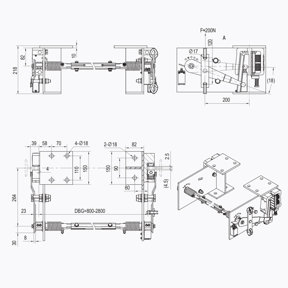 LSD07 Governor-Triggered Safety Gear SystemDual-link system that works with an overspeed governor to trigger safety gear; relevant when checking rope grip and linkage response.View Product →
Reset is not the end of the event. After any trip under load, measure wedge lift and rod straightness before the car returns to service.
Speed, Stroke and Synchronization: The Numbers That Decide
Three figures define whether a linkage is doing its job: the governor tripping envelope, the deceleration band at the rails, and the stroke remaining at full wedge lift.
The chart shows why high-speed jobs are harder on the linkage than low-speed jobs. At 1.00 m/s the governor may trip anywhere between 1.15 and 1.50 m/s, a window of 0.35 m/s. At 6.00 m/s the permitted window runs from 6.90 to 7.54 m/s, and the tripping force available at that speed arrives in a much shorter time. The linkage has to convert a sharper impulse into the same smooth wedge lift.
Stroke is the figure that does not appear in the standard, and it is the one that fails quietly. The linkage must lift each wedge through its full working stroke while travel remains in reserve. If the linkage bottoms out before the wedge reaches full lift, the remaining pull goes into the rods instead of the rails, and the safety gear never reaches its rated clamping force.
Measure the reserve on both sides with the same gauge. An unequal reading points to the equalizing lever or one side rod, never to the safety gear.
Configuring the Linkage for Different Elevator Types
Linkage configuration changes with the elevator type, because wedge mass, governor rope length and available frame space all change with it.
Short governor ropes and tight frame space dominate. The linkage needs a low trip force and light return springs, and the adjusting points must be reachable without removing the car top handrail.
High wedge mass and heavy guide rails raise the pull required. Rods are thicker, the equalizing lever is reinforced, and pin clearances are held tighter because a heavy wedge amplifies any asymmetry.
Long governor ropes stretch and move more, so rope slack and elongation compensation dominate the design. The linkage must absorb rope movement without spending its own stroke budget.
Shanghai Liftech Elevator Accessories Co., Ltd., trading as Liftech, builds the LSD and LLD families of linkage devices for these three application groups, alongside the safety gears, governors and tension devices they connect to. The elevator safety linkage device range lists the individual models by function, including governor-triggered systems, brake actuation linkages and release devices.
Match the linkage to the wedge, not to the car. A linkage sized for a 4 kN wedge will not lift a freight wedge rated for twice that force, however well it is adjusted.
Inspection and Reset in the Field
Six checks cover the linkage on a routine maintenance visit, and all six can be completed with the car parked and the power isolated.
- Move the equalizing lever by hand and confirm it pivots freely with no binding or rock in the pin.
- Measure wedge lift on both sides and confirm each wedge reaches the full stroke stated by the manufacturer.
- Inspect every pin and bushing for visible clearance, corrosion or a polished wear ring.
- Verify the rope grip holds the governor rope without slipping when a test pull is applied.
- Check the return springs against their free length; discard any spring that has taken a permanent set.
- Trip-test the electrical contact and confirm the drive cannot start while the linkage is in the tripped position.
After any trip under load, the assembly needs a re-measure rather than a visual glance. Rod straightness, pin clearance and wedge lift on both sides should be recorded and compared with the commissioning figures. The governor connection and linkage function guide covers the force path in more detail for engineers writing acceptance criteria.
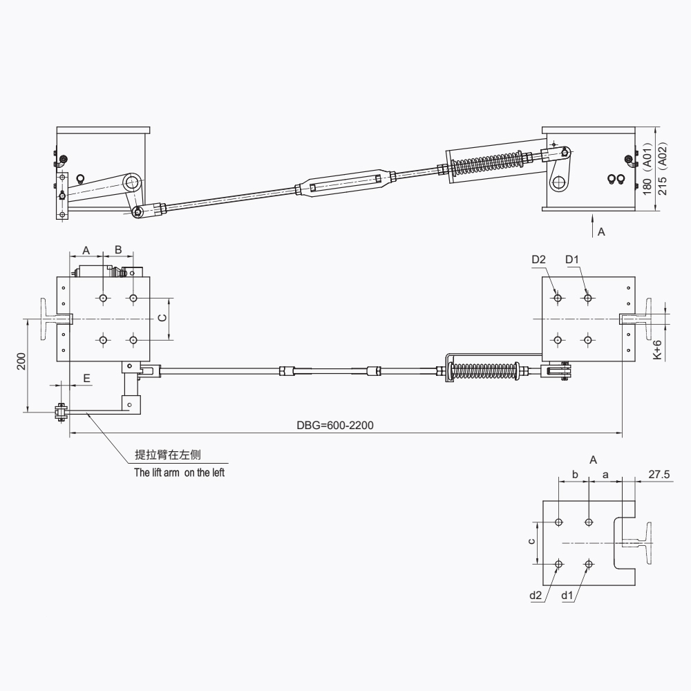 LSD12 Lift Safety Gear Release DeviceRelease device for resetting tripped safety gear and linking both-side clamps; check unobstructed release travel before returning the car to service.View Product →
Release devices exist because a tripped safety gear must be reset by a person, not by the machine. Confirm the release travel is unobstructed before the car is put back into service.
Practical Questions Engineers Ask
How is a safety gear linkage mechanism different from the safety gear itself?
The safety gear is the clamping device that grips the guide rails; the linkage is the transmission that lifts both clamping wedges. A progressive safety gear rated for 1.0 g of deceleration will not deliver that figure if the linkage lifts one wedge before the other, because the car tilts and the load transfers to a single rail. The two parts are type-tested together under EN 81-50:2014 and should be adjusted as a matched set.
How much stroke should be left at full wedge lift?
Set the linkage so each wedge reaches full lift with travel still in reserve, and never use spring preload to take up slack. If the linkage bottoms out before the wedge reaches full lift, the pull is absorbed by the rods instead of the rails. Check the reserve on both sides with the same gauge; an unequal reading means the equalizing lever or one side rod is out of adjustment.
Why does the linkage carry an electrical safety contact?
The contact proves the linkage is back in the released position before the drive may start. EN 81-20 requires the machine to be stopped and kept stopped while the safety gear is applied, and the linkage switch is the interlock that enforces it. A contact adjusted to close early is a defect, not a convenience.
Can a tripped linkage be repaired on site?
Reset yes, repair no for most damage. Bent pull rods, seized pins, cracked levers and springs with permanent set are replacement items. After any trip under load, measure rod straightness, pin clearance and wedge lift on both sides, and record the values against the commissioning figures before the car re-enters service.
A linkage that is measured, recorded and adjusted on schedule is the cheapest safety upgrade available on any existing car.