
 English
 中文简体
 русский
 Español
 Deutsch



Custom Elevator Rope Brake: Applications, Selection Criteria, and Practical Guidance
Content
- 1 What a Custom Elevator Rope Brake Actually Is
- 2 Where a Rope Brake Earns Its Place
- 3 The Seven Parameters That Decide a Custom Build
- 4 Clamping Force and What It Does to the Rope
- 5 How Much Stopping Distance the Device Needs
- 6 Control, Release and Monitoring Logic
- 7 How Liftech Approaches a Custom Rope Brake Order
- 8 What to Check Before You Sign Off
- 9 Questions Buyers Ask About Rope Brakes
On a 1.6 m/s machine-room-less lift with five 8x19S traction ropes, a rope brake either holds 125 percent of rated load or it slips, and which of the two happens is decided in the clamping force calculation and the jaw groove tolerance, not on site.
Most custom elevator rope brake enquiries arrive the same way. A modernisation contractor needs to close an unintended car movement gap, or an OEM wants a braking path that never touches the guide rails, and the catalogue unit does not match the rope set already hanging in the shaft. The order then turns into an engineering exercise: rope diameter, rope construction, car mass, actuation source and controller interface all have to be fixed before a drawing can be issued.
Liftech, registered as Shanghai Liftech Elevator Accessories Co., Ltd. and manufacturing in Zhejiang, has built elevator safety components since 2004, and its rope brake work sits alongside safety gears, overspeed governors and oil buffers rather than on its own. That matters, because a rope brake is only as reliable as the governor and linkage that release it.
What a Custom Elevator Rope Brake Actually Is
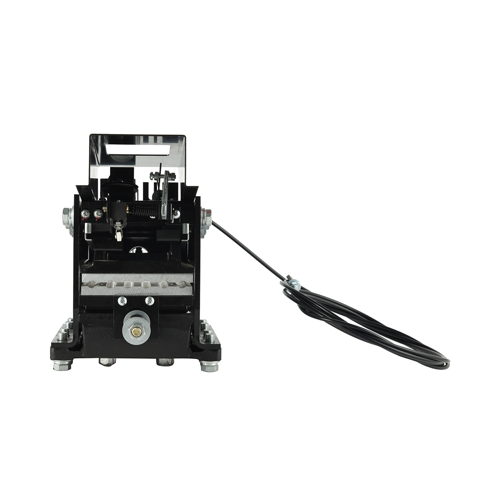
A custom elevator rope brake is a rope-clamping safety device engineered around one specific rope set, one load case and one control interface, instead of a catalogue part with fixed jaw geometry. It grips the suspension ropes directly, so every force it generates has to be matched to rope diameter, rope construction, rope count and the mass it is expected to stop.
Definition: an elevator rope brake, also sold as a lift rope gripper or rope clamp, is a safety component that clamps the traction ropes or the governor rope to hold or stop the car. Under EN 81-20:2020 clause 5.6.2 it can serve as the protective device against unintended car movement with the landing doors open.
A traction lift carries three independent braking paths. The machine brake acts on the traction sheave, the safety gear acts on the guide rails, and the rope brake acts on the ropes themselves. Because it does not depend on rail condition or sheave lining, it is the path most independent of the rest of the installation. The working principle, including how the jaws convert a small solenoid stroke into a large clamping force, is covered in the Liftech guide to how rope brakes arrest a moving car.
The distinction customers most often miss is that a rope brake is not a parking brake and not a substitute for a worn machine brake. It is a second, monitored stop that is expected to work perhaps a few times in the life of a lift, and it must still work after years of sitting idle in an oily shaft.
Where a Rope Brake Earns Its Place
A rope brake justifies its cost in three situations: unintended car movement protection on new machine-room-less lifts, modernisation work guided by EN 81-80:2003, and heavy-load or high-speed installations that need a braking action independent of the guide rails.
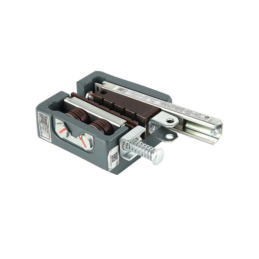
Traction-rope gripper
- Clamps four to eight suspension ropes in one action
- Mounts on the car frame or the counterweight frame
- Force per rope must stay inside the rope surface pressure limit
- Serves as the UCMP protective device on most MRL designs
- Needs clear rope length and jaw access for inspection
Governor-rope gripper
- Clamps a single governor rope, typically 6 to 6.5 mm
- Lower clamping force and smaller coil current
- Common in retrofit kits and holding functions
- Triggers the linkage that lifts the safety gear
- Easier to fit when car-top space is tight
For a retrofit, the deciding factor is usually rope condition rather than space. A 15-year-old rope set that has already lost 3 percent of its nominal diameter will not give the jaw the contact pattern it was designed for, and no amount of clamping force compensates for that.
The Seven Parameters That Decide a Custom Build
Seven parameters fix the geometry, the force and the electrical interface of a custom rope brake, and each one changes the drawing rather than just the price. Collecting them before the first technical exchange removes most of the back-and-forth that slows a custom order down.
| Parameter | Why it changes the design | What to send |
| Rope diameter and construction | Jaw grooves are machined to the rope; 8x19S and 6x19S sit differently | Diameter in mm, construction, core type, lubrication state |
| Rope count and pitch | Sets jaw quantity, frame width and how force is shared | Number of ropes, centre distance between ropes |
| Rated load and car mass | Drives the clamping force target and the test load | Rated load in kg, car weight, suspension ratio |
| Actuation source | Decides whether the unit is solenoid, spring or governor driven | UCMP node output, governor model, manual release requirement |
| Electrical interface | Must match the controller monitoring circuit | Coil voltage, current draw, contact type |
| Mounting envelope | Jaw travel and release lever both need free space | Car top height, distance to first rope clamp, headroom |
| Shaft environment | Oil, dust and temperature all shift the friction coefficient | Rope condition, ambient temperature, required IP rating |
The LRB02 family from Liftech is the usual starting point for these builds: a rope brake, lift rope gripper and rope clamp platform that is adapted to the rope set and control interface of each project rather than shipped as a fixed unit.
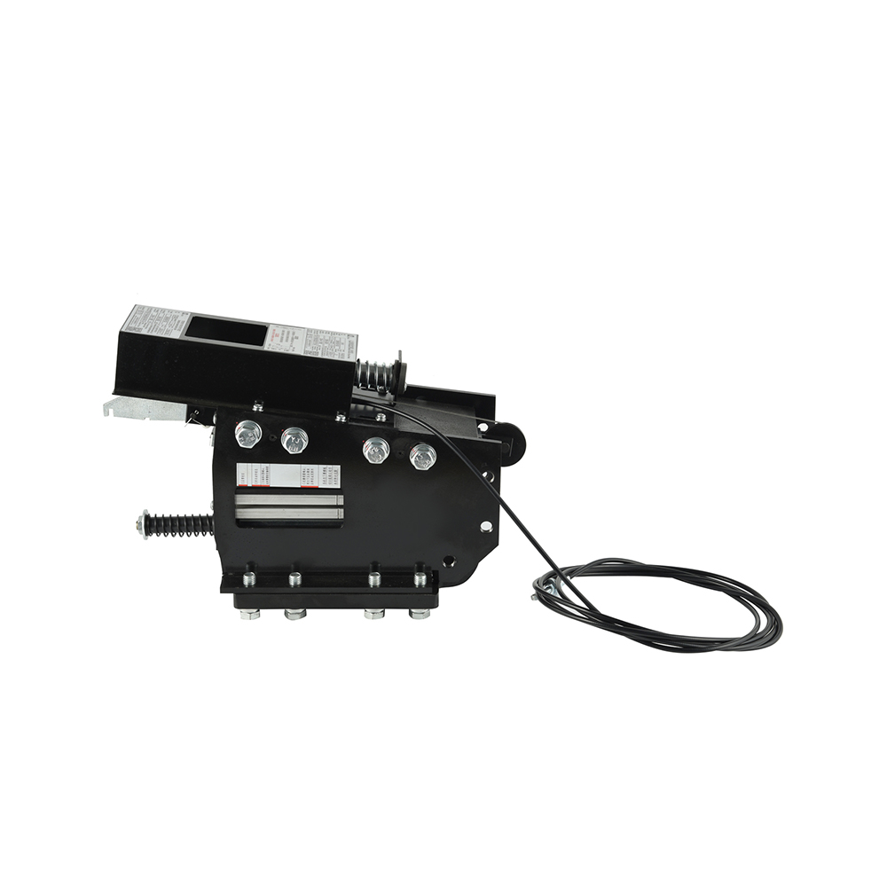 LRB02 Elevator Rope Brake and Rope Clamp PlatformConfigurable rope brake, gripper and clamp platform adapted to each project's rope set and control interface.View Product →
Clamping Force and What It Does to the Rope
Clamping force is set by the heaviest load the device must hold and limited by the pressure the rope can take without permanent deformation, and both numbers are fixed by the rope rather than by the brake.
Take a 1000 kg rated load on a 1300 kg car. The static load is 2300 kg, roughly 22.6 kN, and across five ropes that is about 4.5 kN per rope. With a steel-on-steel friction coefficient near 0.15, the jaws need around 30 kN of normal force per rope to hold that load; with a polymer lining at roughly 0.30, the same duty needs about 15 kN. This is why jaw lining material is specified explicitly and never left to the supplier's default.
Two numbers decide whether a rope brake holds: the clamping force it can generate, and the friction coefficient of the rope surface it meets. Oil on the ropes removes the second one entirely, which is why a 125 percent load test on a lubricated rope set is the only test worth accepting.
- Measure rope diameter at three points along the rope; worn rope below nominal changes groove fit
- Ask for the rope certificate under EN 12385-5 or ISO 4344, which gives construction and minimum breaking load
- State the jaw lining material in writing; steel jaws need roughly double the force of polymer jaws
- Require a 125 percent holding test on the assembled unit, not on a prototype
- Inspect ropes for broken wires after any dynamic test and compare with the discard criteria in EN 81-20:2020
How Much Stopping Distance the Device Needs
At the minimum average deceleration of 0.2 g used for progressive safety gear, a car moving at 1.6 m/s covers about 0.65 m before it stops, and that distance has to exist inside the shaft, above the buffer and below the top landing.
Free stopping distance at 0.2 g average deceleration
Calculated from the kinematic relation s = v squared divided by 2a, with a equal to 0.2 g. Reaction time, machine brake contribution and buffer stroke are excluded, so real stopping distance is longer.
Two practical conclusions follow. First, a rope brake that clamps instantly but ramps force slowly will overshoot the available distance, which is why force build-up curves are requested in the technical file. Second, deceleration above roughly 1.0 g is outside the range a passenger car should ever produce, so a rope brake tuned for a freight lift should never be reused unchanged on a passenger unit of the same load.
Control, Release and Monitoring Logic
A rope brake must close on command or on loss of power, confirm closure with a positive-opening contact, and then hold until a competent person releases it manually.
- Detection. The governor or the UCMP node registers car movement with the landing doors unlocked.
- Command. The controller removes coil voltage, and a spring or stored-energy mechanism drives the jaws closed.
- Clamp. The jaws contact the ropes and force rises to the set value within the specified actuation time.
- Confirmation. A positive-opening contact signals the clamped state, and the machine brake sets afterwards.
- Release. A service lever or hand pump releases the jaws, and the unit resets only after a manual action.
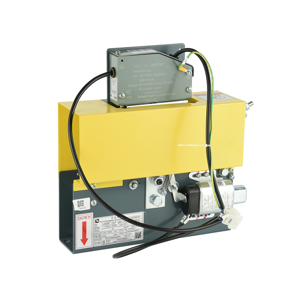
The triggering side matters as much as the gripper. On a UCMP application the governor provides the movement signal, and Liftech supplies the LUC03 governor for exactly that interface, while the actuation path from governor to brake is handled by linkage hardware such as the LSD08 emergency brake actuation system.
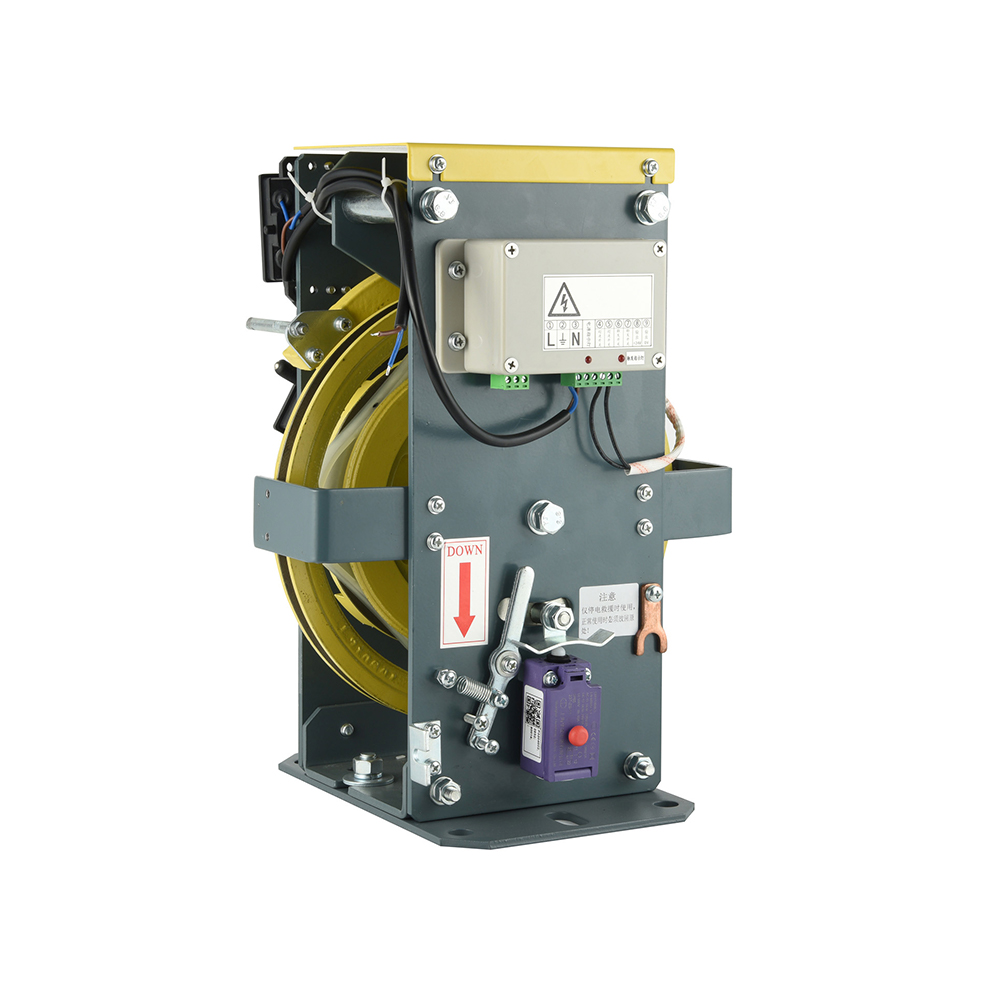 LUC03 Overspeed Governor for UCMP Elevator SystemsCam-based UCMP governor provides mechanical two-way triggering and selectable 220VAC or 24VDC supply for machine-room elevator applications.View Product →
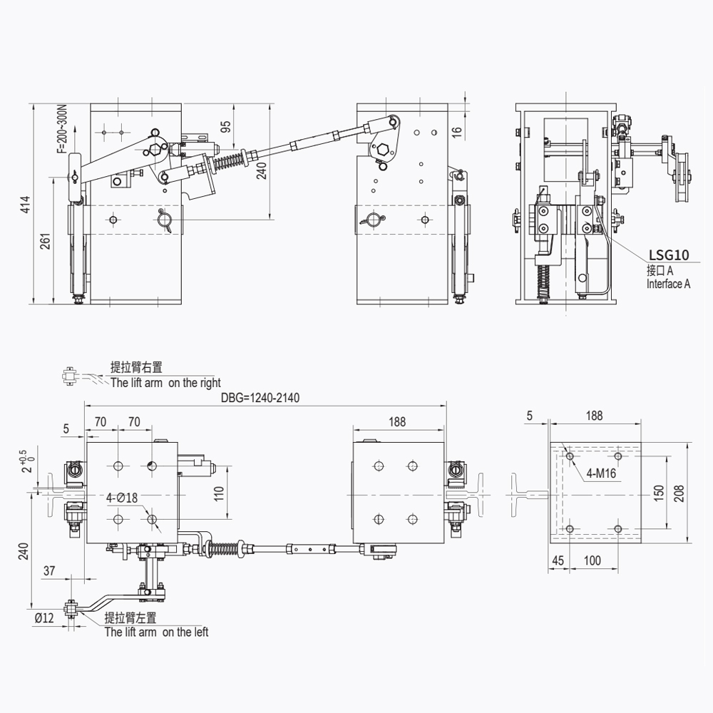 LSD08 Emergency Brake Actuation System for LiftsMechanical linkage actuation system for triggering the safety clamp when an elevator overspeeds or experiences abnormal movement.View Product →
One detail decides whether the whole chain passes commissioning: the monitoring contact must be wired as a positive-opening type. A spring-return microswitch that sticks closed after a clamping event will let the controller release the machine brake while the jaws are still gripping.
How Liftech Approaches a Custom Rope Brake Order
Liftech has manufactured elevator safety components since 2004, completed its four-family safety portfolio of safety gears, overspeed governors, oil buffers and rope brakes in 2015, and reported annual output above RMB 150 million in 2023.
That history explains the way rope brake orders are handled. Because the company also builds the governors, linkages and tension devices that sit upstream of the gripper, a rope brake enquiry is reviewed against the entire stopping chain rather than as an isolated part. A custom LRB02 variant is normally defined by rope set, force target, actuation source and mounting envelope, and the full product range is listed on the Liftech elevator safety components homepage.
- Founded in 2004 by an engineering team drawn from the elevator industry
- Four safety component families completed in 2015, rope brakes included
- Annual output above RMB 150 million reported for 2023
- Product documentation and enquiries handled in English, Chinese, Russian, Spanish and German
What to Check Before You Sign Off
Six checks separate a rope brake that will pass commissioning from one that will generate a callback, and all six can be completed before the car is handed over.
- Rope diameter measured at three points and recorded against the certificate
- Jaw lining material confirmed in writing against the friction coefficient used in the force calculation
- 125 percent holding test performed on the assembled unit with the ropes in their final condition
- Actuation time measured and compared with the value stated in the technical file
- Monitoring contact verified as positive-opening and witnessed by the inspector
- Manual release lever reachable from the car top without removing the rope guard
Questions Buyers Ask About Rope Brakes
What load must a rope brake hold during a type test?
125 percent of rated load. EN 81-20:2020 clause 5.6.2 requires the protective device against unintended car movement to stop and hold the car at that load, and EN 81-50:2020 sets out the corresponding test procedure. A unit that only demonstrates holding at rated load has not been tested against the clause.
Can a rope brake be retrofitted to an existing lift?
Yes, and EN 81-80:2003 provides the improvement framework for existing installations. Two conditions apply: the ropes must pass inspection for broken wires and diameter loss, and the jaw groove must be machined for the rope construction actually installed, not for the construction shown on the original drawing.
Does clamping damage the traction ropes?
Not when surface pressure stays inside the rope manufacturer's limit. A polymer-lined jaw distributes pressure better than a steel jaw and needs roughly half the normal force for the same holding duty. After any dynamic test, inspect for broken wires and diameter reduction against the discard criteria in EN 81-20:2020 before returning the lift to service.
What information speeds up a custom quote?
Five items shorten a custom rope brake quote to a single exchange: rope diameter and construction, rope count and pitch, rated load with car mass, actuation source, and coil voltage with contact type. Suppliers who receive all five can usually issue a drawing without a second round of questions.