 English
 中文简体
中文简体 русский
 Español
 Deutsch

How Do Elevator Rope Brakes Prevent Falls?
Content
- 1 Fundamental Operating Principles
- 2 Elevator Rope Gripper Safety Device Engineering
- 3 Electromagnetic Elevator Rope Brake System Architecture
- 4 Elevator Overspeed Rope Brake Supplier Evaluation
- 5 Bi Directional Elevator Rope Gripper Applications
- 6 Elevator Emergency Rope Brake Installation Protocols
- 7 Type Testing and Certification Processes
- 8 Maintenance and Lifecycle Management
- 9 Frequently Asked Questions
- 9.1 How do elevator rope brakes comply with EN 81-20/50 requirements?
- 9.2 Can rope brakes integrate with existing elevator safety circuits?
- 9.3 What customization options exist for high-rise applications?
- 9.4 What is the service life expectancy of elevator rope gripper safety devices?
- 9.5 How does unintended car movement protection (UCMP) relate to rope brake function?
- 10 References
Elevator Rope Brake systems represent critical safety mechanisms in vertical transportation, preventing car descent in the event of rope failure or overspeed conditions. This technical examination explores engineering principles, regulatory frameworks, and procurement considerations for B2B buyers in the elevator industry.
Fundamental Operating Principles
Mechanical vs. Electromagnetic Actuation
Modern rope brakes employ two primary actuation methodologies. Mechanical systems utilize centrifugal governors or mechanical speed switches, while electromagnetic configurations integrate with electronic safety circuits for enhanced response precision.
Actuation System Comparison:
| Parameter | Mechanical Actuation | Electromagnetic Actuation |
| Response Time | 150-300 ms | 50-100 ms |
| Power Dependency | None (self-acting) | Requires electrical supply |
| Maintenance Requirements | High (moving parts) | Moderate (electrical components) |
| Reset Procedure | Manual, on-site | Remote or automatic possible |
| Cost (relative) | 1.0x (baseline) | 1.3-1.6x |
| Temperature Sensitivity | Low (-20°C to 60°C) | Moderate (coil resistance variation) |
Regulatory Compliance Matrix
International standards govern rope brake performance and certification. EN 81-20/50 mandates type testing for all safety components, while ASME A17.1 specifies additional requirements for North American installations.
- EN 81-20: Safety rules for construction and installation of lifts—Lifts for the transport of persons and goods
- EN 81-50: Design rules, calculations, examinations and tests of lift components
- ASME A17.1: Safety Code for Elevators and Escalators
- ISO 8100-1: Safety parameters meeting global essential safety requirements
Elevator Rope Gripper Safety Device Engineering
The elevator rope gripper safety device functions as a uni-directional or bi-directional clamping mechanism, engaging hoist ropes when predetermined speed thresholds are exceeded or when unintended car movement is detected.
Grip Force Mechanics
Clamping force must exceed rope breaking load with adequate safety margin while preventing rope deformation. Typical engagement forces range from 15-25 kN for standard applications, scaling to 40+ kN for high-capacity freight installations.
Gripper Configuration Specifications:
| Rope Diameter (mm) | Min. Grip Force (kN) | Contact Pressure (MPa) | Jaw Material |
| 8-10 | 15 | 120-150 | Hardened steel 58-62 HRC |
| 11-13 | 22 | 140-170 | Hardened steel 58-62 HRC |
| 14-16 | 30 | 160-190 | Carbide-inserted steel |
| 17-20 | 40 | 180-220 | Carbide-inserted steel |
Rope Surface Preservation
Jaw serration geometry (60° included angle, 0.5mm pitch) provides mechanical interlock without fiber cutting. Surface hardness differential between jaw (60 HRC) and rope wire (45-50 HRC) ensures sacrificial wear occurs on replaceable gripper components rather than permanent rope damage.
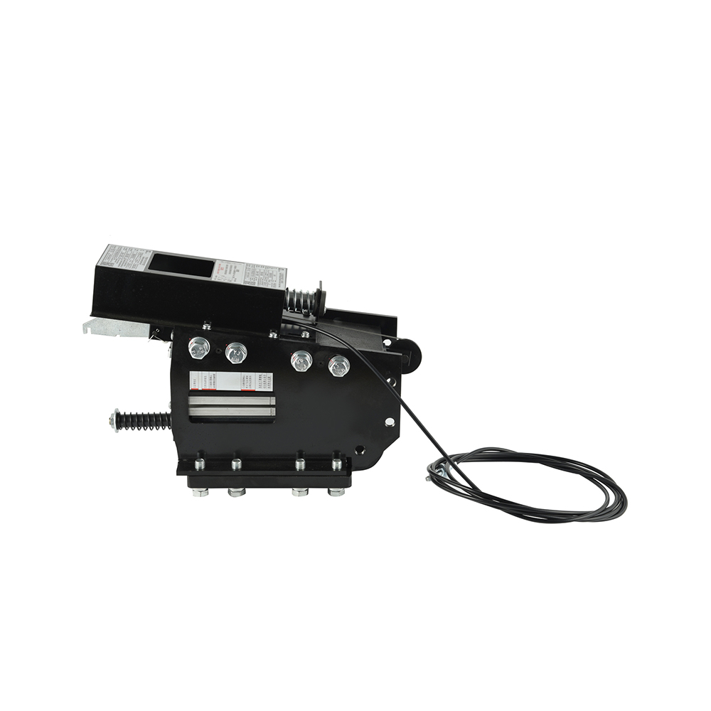
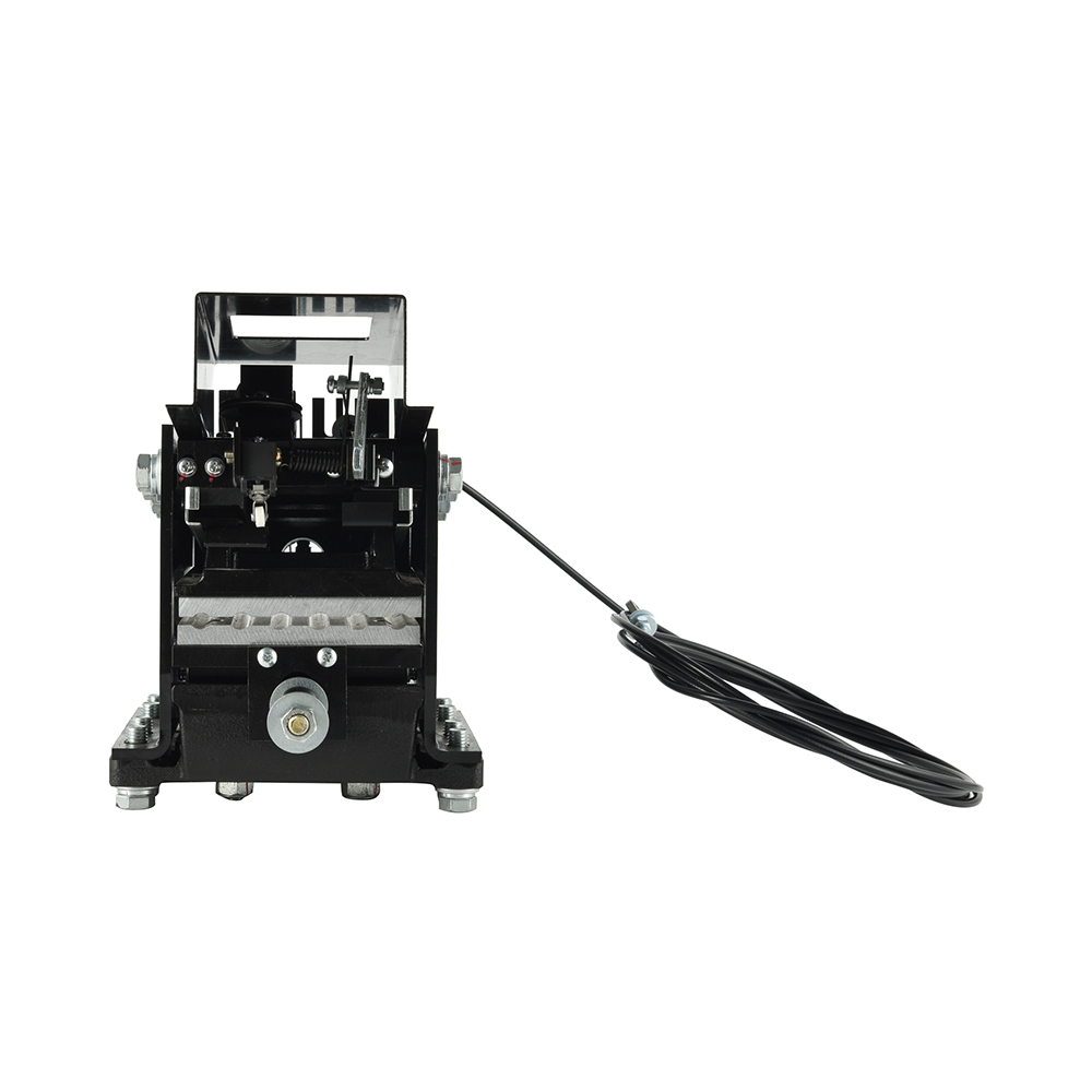
Electromagnetic Elevator Rope Brake System Architecture
Electromagnetic elevator rope brake systems utilize solenoid-actuated clamping mechanisms, offering precise control integration with elevator safety circuits and reduced mechanical complexity compared to purely mechanical alternatives.
Solenoid Engineering Parameters
DC solenoids (24V or 48V nominal) provide consistent force regardless of stroke position. Coil insulation class F (155°C) ensures thermal stability during sustained holding periods.
Solenoid Specifications:
| Parameter | Standard Duty | Heavy Duty |
| Nominal Voltage | 24 VDC | 48 VDC |
| Holding Force (N) | 800-1,200 | 1,500-2,500 |
| Power Consumption (holding) | 15-25W | 30-50W |
| Insulation Class | F (155°C) | H (180°C) |
| Duty Cycle | 100% ED | 100% ED |
| IP Rating | IP54 | IP65 |
Fail-Safe Design Logic
Spring-applied, electrically-released (SAER) configurations ensure automatic engagement upon power loss. Dual-channel safety relays with forced-guided contacts monitor solenoid health, triggering immediate brake application if coil continuity fails.
Elevator Overspeed Rope Brake Supplier Evaluation
Selecting an elevator overspeed rope brake supplier requires verification of manufacturing capabilities, testing infrastructure, and certification validity. Production precision directly impacts safety system reliability.
Manufacturing Quality Systems
ISO 9001 certification provides baseline quality management assurance. However, elevator safety component manufacturing demands additional process controls:
- CNC Machining Tolerance: ±0.02mm for critical mating surfaces
- Heat Treatment Verification: Hardness testing per batch, not sampling
- Spring Rate Consistency: ±5% force variation across production lot
- Electrical Testing: 100% coil resistance and insulation verification
Founded in 2004, Shanghai Liftech Elevator Accessories Co., Ltd. is a specialized enterprise dedicated to the R&D, manufacturing, testing, and sales of elevator safety components. Our facility maintains comprehensive in-house testing capabilities including dynamic drop towers and electromagnetic compatibility chambers.
Type Testing Documentation
Valid type test certificates (per EN 81-50) must accompany each product variant. Certificate review should verify:
- Test laboratory accreditation (ISO/IEC 17025)
- Scope coverage for declared rope diameter range
- Maximum rated speed validation
- Temperature cycling test completion (-10°C to 55°C)
Bi Directional Elevator Rope Gripper Applications
Bi directional elevator rope gripper systems monitor and respond to both upward and downward overspeed conditions, essential for traction elevators with machine-room-less (MRL) configurations where unintended upward movement presents equivalent hazard to free-fall.
Speed Monitoring Architecture
Dual-directional operation requires independent speed sensing for each direction. Encoder-based systems (1024 PPR minimum) provide 0.5% speed accuracy, while centrifugal governors require separate cam profiles for upward and downward activation.
Directional Performance Specifications:
| Direction | Activation Speed (% of rated) | Permitted Overshoot | Test Method |
| Downward | 115% | +3% | Controlled descent with rated load |
| Upward | 115% | +3% | Controlled ascent with empty car |
| Unintended Movement | 0.3 m/s (fixed) | +0.05 m/s | UCMP test per EN 81-20 |
Symmetrical vs. Asymmetrical Design
Symmetrical grippers utilize identical jaw geometries for both directions, simplifying manufacturing but requiring compromise in optimal grip angle. Asymmetrical designs employ direction-specific jaw profiles, maximizing grip efficiency (15-20% force reduction for equivalent holding capacity) at increased tooling cost.
Elevator Emergency Rope Brake Installation Protocols
Proper elevator emergency rope brake installation ensures designed performance under emergency conditions. Positioning, alignment, and integration errors compromise safety function.
Mounting Position Engineering
Rope brakes install at either car (ascending car overspeed protection) or traction sheave (descending direction). Car-mounted units require structural analysis of car frame load paths; sheave-mounted configurations demand verification of bearing load increases.
Installation Position Comparison:
| Mounting Location | Protection Direction | Structural Impact | Maintenance Access |
| Car Top | Upward overspeed | Car frame bending moment | Requires pit or roof access |
| Traction Sheave | Downward overspeed | Bearing load increase 15-20% | Machine room access |
| Counterweight | Upward (car empty) | CWT frame reinforcement | Hoistway access required |
Rope Alignment Tolerances
Jaw centerline must align with rope centerline within ±1.0mm to prevent uneven loading. Angular misalignment must not exceed 0.5° to ensure full jaw contact across rope diameter.
With over two decades of sustained development, Liftech has established itself as a leading manufacturer in China's elevator safety sector, providing high-quality products and solutions to a wide range of major elevator brands and engineering clients across domestic and international markets. Our technical support team provides installation supervision and commissioning verification to ensure optimal system performance.
Type Testing and Certification Processes
Comprehensive validation ensures elevator rope brake reliability across service life. Testing protocols exceed operational stresses to demonstrate safety margins.
Dynamic Drop Testing
Type tests simulate rope failure at 125% rated speed with 100% rated load. Brake must arrest car within specified stopping distance (typically <1.0m for rated speed ≤1.0 m/s) without rope slippage exceeding 50mm.
Test Sequence Requirements:
- Static Grip Test: 2x breaking load, 10-minute hold, zero slippage
- Dynamic Engagement: 100 consecutive cycles at rated speed
- Temperature Cycling: Operation after -10°C and +55°C exposure
- Dust Contamination: Function verification per EN 60529 IP5X
- Endurance Testing: 100,000 mechanical cycles without adjustment
Certification Traceability
Production units must maintain traceability to type-tested designs through:
- Material certificates for critical components (jaws, springs, coils)
- Dimensional inspection records against type test samples
- Serial number tracking linking to manufacturing batch
Maintenance and Lifecycle Management
Inspection Protocols
EN 81-20 mandates periodic examinations of safety components. Rope brake inspection intervals align with elevator maintenance categories:
| Maintenance Category | Inspection Interval | Critical Inspection Points |
| Standard Service | 12 months | Jaw wear, spring force, coil resistance |
| Heavy Service | 6 months | Additional: contact surface inspection |
| Severe Service | 3 months | Full disassembly and dimensional check |
Wear Indicators and Replacement Criteria
Jaw replacement required when serration depth reduces 30% from original. Spring replacement when free length changes 5% or force-rate decreases 10%. Coil replacement when resistance varies ±10% from nominal or insulation resistance falls below 1 MΩ.
Frequently Asked Questions
How do elevator rope brakes comply with EN 81-20/50 requirements?
Compliance requires valid type test certification per EN 81-50, installation verification against type-tested configuration, and maintenance adherence to manufacturer specifications. Electromagnetic elevator rope brake systems must additionally demonstrate SIL 3 capability (EN 61508) when integrated into safety circuits. Our products carry EU-type examination certificates issued by Notified Bodies.
Can rope brakes integrate with existing elevator safety circuits?
Integration requires compatibility assessment of voltage levels, contact ratings, and safety category requirements. Modern bi directional elevator rope gripper systems utilize forced-guided relays (EN 60947-5-1) compatible with most safety PLC inputs. Retrofit installations may require circuit modification to accommodate dual-channel monitoring.
What customization options exist for high-rise applications?
High-rise installations (travel >100m) require enhanced response speed and heat dissipation. Customizations include: high-speed actuation (response <50ms), forced-air cooling for sheave-mounted units, and redundant gripper configurations (2x 75% capacity vs. 1x 150%). As a specialized elevator overspeed rope brake supplier, we provide application engineering for super-tall building projects.
What is the service life expectancy of elevator rope gripper safety devices?
Design life is 20 years or 2 million cycles, whichever occurs first. Actual service life depends on activation frequency—units in high-traffic installations may require component replacement at 10-12 years. Regular inspection identifies degradation before safety margins are compromised.
How does unintended car movement protection (UCMP) relate to rope brake function?
UCMP systems detect car movement with doors open and trigger stopping action. Elevator emergency rope brake installation for UCMP typically utilizes car-mounted grippers with electronic speed monitoring (0.3 m/s threshold). UCMP rope brakes require additional testing per EN 81-20 Annex G, including verification of stopping distance with empty car and 125% rated load.
References
- European Committee for Standardization. (2020). EN 81-20:2020 Safety rules for the construction and installation of lifts—Lifts for the transport of persons and goods—Part 20: Passenger and goods passenger lifts. Brussels: CEN.
- European Committee for Standardization. (2020). EN 81-50:2020 Safety rules for the construction and installation of lifts—Design rules, calculations, examinations and tests of lift components. Brussels: CEN.
- American Society of Mechanical Engineers. (2022). ASME A17.1-2022 Safety Code for Elevators and Escalators. New York: ASME.
- International Organization for Standardization. (2019). ISO 8100-1:2019 Lifts for the transport of persons and goods—Part 1: Safety parameters meeting the global essential safety requirements (GESRs). Geneva: ISO.
- International Electrotechnical Commission. (2010). IEC 61508-1:2010 Functional safety of electrical/electronic/programmable electronic safety-related systems—Part 1: General requirements. Geneva: IEC.
- Liftinstituut. (2023). Testing and Certification of Elevator Safety Components: Technical Guidelines for Manufacturers. Amsterdam: Liftinstituut.


