 English
 中文简体
中文简体 русский
 Español
 Deutsch

What Is Elevator Safety Gear?
Content
Safety gear elevator systems are the last line of mechanical defense in a vertical transportation safety chain. When all other protective systems—speed limiters, brake systems, and electrical interlocks—fail to prevent an elevator car or counterweight from exceeding rated speed in the downward direction, the safety gear elevator mechanism is the device that physically arrests the motion by clamping onto the guide rails with sufficient force to bring the loaded car to a controlled stop within defined deceleration limits. Without a correctly specified, installed, and maintained safety gear elevator assembly, no elevator installation can be considered safe for public use under any major regulatory framework.
This technical guide provides an engineer-level examination of safety gear elevator systems—covering operating principles, type classification, component specifications, inspection protocols, maintenance requirements, and global certification standards relevant to elevator manufacturers, engineering contractors, and maintenance organizations worldwide.
1. How Elevator Safety Gear Works
1.1 Core Operating Principle
The safety gear elevator mechanism operates on the principle of friction-induced deceleration through controlled clamping force applied to the guide rails. The device is mounted on the elevator car frame (and in some configurations, on the counterweight frame) and remains in a passive, non-engaged state during all normal elevator operation. Engagement is triggered exclusively by an overspeed condition detected by the speed governor system.
When engaged, the safety gear jaw elements—whether roller, wedge, or eccentric disc type—are driven into contact with the guide rail running surfaces by the mechanical action of the governor rope linkage. The resulting normal force between the jaw elements and the rail generates a friction force opposing the downward motion of the car. For a correctly specified safety gear, this friction force is sufficient to decelerate the fully loaded car from the trigger speed to zero within the deceleration limits prescribed by the applicable standard (typically 0.2g to 1.0g for progressive types).
1.2 Trigger Mechanism: Governor Rope and Overspeed Detection
The speed governor is a centrifugal mechanical device mounted in the machine room or overhead structure, connected to the elevator car via a closed-loop governor rope that runs continuously during car travel. As car speed increases, centrifugal force acting on the governor flyweights causes them to pivot outward. At the rated trigger speed—set at a minimum of 115% of the elevator's rated speed per EN 81-20 and equivalent standards—the flyweights reach a displacement threshold that trips a mechanical latch, arresting the governor sheave and the governor rope.
With the governor rope arrested and the car continuing downward, the rope is placed in tension relative to the car frame. This tension is transmitted through a linkage mechanism (typically a pull rod and lever arm system) to the safety gear jaws, driving them into engagement with the guide rails. The entire sequence from governor trip to full safety gear engagement occurs within milliseconds and requires no electrical power or electronic control input—a deliberate design requirement ensuring operation during power failure scenarios.
1.3 How Safety Gear Engages the Guide Rails
Guide rail engagement is the critical mechanical event in the safety gear elevator activation sequence. The jaw elements must achieve consistent, uniform contact with both rail running surfaces simultaneously to prevent car rotation or uneven deceleration that could injure passengers or damage the installation. Key engagement parameters include:
- Jaw contact pressure distribution: For progressive safety gear, the contact pressure must be distributed across a defined jaw face area to keep rail surface stress below the yield strength of the rail material (typically S235 or S355 structural steel per EN 10025).
- Self-energizing geometry: Most safety gear jaw designs incorporate a self-energizing wedge angle that causes increasing normal force as the jaw penetrates further onto the rail under downward load—ensuring the clamping force increases proportionally with the deceleration demand rather than remaining fixed.
- Symmetrical engagement: Both safety gear units (one on each side of the car frame) must engage simultaneously. Differential engagement timing causes car tilt, which is addressed by mechanical synchronization linkages connecting both units to a common pull rod assembly.
1.4 Role of the Buffer and Pit in the Safety Chain
The safety gear elevator system does not operate in isolation—it is one element in a multi-layer safety chain that includes the speed governor, electrical safety circuits, terminal limit switches, and the pit buffer. The buffer (oil hydraulic or polyurethane spring type) provides the final energy absorption stage if the car reaches the pit at reduced speed following safety gear engagement. The pit depth is dimensioned to accommodate the maximum buffer compression stroke plus safety clearances defined by the applicable standard, ensuring that even partial safety gear engagement (which may not fully arrest motion before the pit) does not result in structural damage or passenger injury from impact with the pit floor.
2. Elevator Safety Gear Types and Functions
2.1 Instantaneous Safety Gear — Design and Application
Understanding elevator safety gear types and functions begins with the instantaneous type—the simpler of the two primary classifications. An instantaneous safety gear elevator device achieves car arrest through a single, sudden clamping action that applies full braking force to the guide rails within a very short travel distance (typically 1–3 mm of jaw displacement).
The instantaneous design uses rigid jaw elements—most commonly hardened steel eccentric discs or fixed wedge blocks—that make direct metal-to-metal contact with the guide rail. Because the braking force is applied almost instantaneously without progressive ramping, the deceleration experienced by the car and its contents is abrupt and correspondingly high. This limits instantaneous safety gear application to low-speed elevators where the kinetic energy at trigger speed is sufficiently low that rapid deceleration does not create injury risk for passengers or structural overload risk for the car frame.
Applicable speed range: rated car speed up to 0.63 m/s per EN 81-20, and up to 1.0 m/s for roller-type instantaneous devices with specific design provisions.
2.2 Progressive Safety Gear for Elevator Systems — Design and Application
Progressive safety gear for elevator systems addresses the deceleration control limitation of instantaneous designs by incorporating a controlled-force spring or elastomeric damping element between the trigger linkage and the jaw assembly. This intermediate compliance element allows the jaw engagement force—and therefore the car deceleration—to build progressively over a defined stopping distance rather than instantaneously.
The progressive safety gear for elevator systems maintains car deceleration within a prescribed range (0.2g to 1.0g per EN 81-20 Annex D) throughout the braking event, regardless of variations in car load, speed at trigger, or guide rail surface condition within the specification range. This controlled deceleration profile protects passengers from injury, prevents structural overload of the car frame, and is mandatory for all elevator installations with rated speeds above 1.0 m/s.
Key design elements of progressive safety gear include:
- Spring package: Calibrated compression spring stacks (typically disc spring / Belleville washer assemblies) that define the maximum and minimum jaw engagement force independent of trigger speed.
- Roller or wedge jaw elements: Hardened steel rollers or precision-machined wedge blocks that translate spring force into controlled rail clamping pressure.
- Adjustable spring preload: Premium progressive designs allow factory-set spring preload adjustment to optimize deceleration performance for specific car mass and speed combinations within a defined range.
- Bilateral symmetry: Both left and right jaw assemblies are mechanically linked to ensure simultaneous, equal engagement force on both guide rails.
2.3 Instantaneous vs Progressive Elevator Safety Gear — Full Comparison
The choice between instantaneous vs progressive elevator safety gear is determined primarily by the elevator's rated speed and the deceleration limits acceptable for the specific application. While instantaneous devices offer simplicity and lower cost, their application is strictly limited by safety standards to low-speed installations. The following comparison covers all relevant engineering and commercial dimensions:
| Parameter | Instantaneous Safety Gear | Progressive Safety Gear |
|---|---|---|
| Applicable rated speed | Up to 0.63 m/s (up to 1.0 m/s for roller type) | All speeds above 1.0 m/s; also used at lower speeds |
| Deceleration profile | Abrupt — very high peak deceleration | Controlled — 0.2g to 1.0g throughout braking |
| Stopping distance | Very short (1–5 mm jaw travel) | Longer (proportional to speed and spring compliance) |
| Passenger injury risk at engagement | Higher (abrupt deceleration shock) | Lower (controlled deceleration within comfort limits) |
| Guide rail wear at engagement | Higher (concentrated contact stress) | Lower (distributed contact over longer engagement path) |
| Mechanical complexity | Low | Medium-High (spring package, precision jaw geometry) |
| Unit cost | Lower | Higher |
| Reset after engagement | Manual reset by qualified technician | Manual reset by qualified technician |
| Typical applications | Goods lifts, low-rise residential, slow service lifts | Passenger elevators, high-rise, high-speed installations |
| EN 81-20 compliance basis | Clause 5.6.2.1 (instantaneous) | Clause 5.6.2.2 (progressive with damped effect) |
2.4 Roller Type vs Wedge Type — Structural Differences
Within both instantaneous and progressive categories, jaw element geometry further differentiates safety gear elevator designs. The two dominant jaw configurations are roller type and wedge type, each with distinct structural characteristics and performance tradeoffs:
| Feature | Roller Type | Wedge Type |
|---|---|---|
| Contact geometry | Cylindrical roller — line contact on rail | Flat or profiled wedge face — area contact on rail |
| Self-energizing mechanism | Roller rolls up inclined ramp under load | Wedge translates up tapered housing under load |
| Rail surface stress | Higher (concentrated line contact) | Lower (distributed area contact) |
| Rail damage at engagement | Scoring marks along rail surface | Controlled surface burnishing over engagement length |
| Sensitivity to rail contamination | Higher (oil/grease reduces roller friction) | Medium (wedge face maintains some grip when lubricated) |
| Typical speed range | Up to 1.0 m/s (instantaneous) or higher (progressive) | 0.63 m/s (instantaneous) to >10 m/s (progressive) |
3. Key Components of an Elevator Safety System
3.1 Speed Governor and Governor Rope
The speed governor is the sensing and triggering element of the safety gear elevator system. It must be type-tested and certified as a complete assembly with the safety gear it is designed to trigger, since the governor trip speed and rope tension characteristics must be matched to the safety gear's engagement force requirements. Critical governor specifications include:
- Trip speed setting: Set at a minimum of 115% of rated car speed (EN 81-20 Clause 5.6.1.2). For rated speeds above 1.0 m/s, the maximum permissible trip speed is defined by a formula based on rated speed, ensuring the governor does not trip so fast that the safety gear stopping distance exceeds the available pit and overhead clearances.
- Governor rope diameter and material: Typically 6–10 mm diameter steel wire rope, selected to provide adequate tensile strength for safety gear actuation force while maintaining the flexibility required for the governor sheave wrap angle. Minimum breaking force must exceed the maximum actuation force by a factor of 8 per EN 81-20.
- Governor rope tension device: A tensioning weight or spring-loaded sheave in the pit maintains consistent governor rope tension throughout the installation's operational life, compensating for rope stretch and preventing false trips or missed engagement due to rope slack.
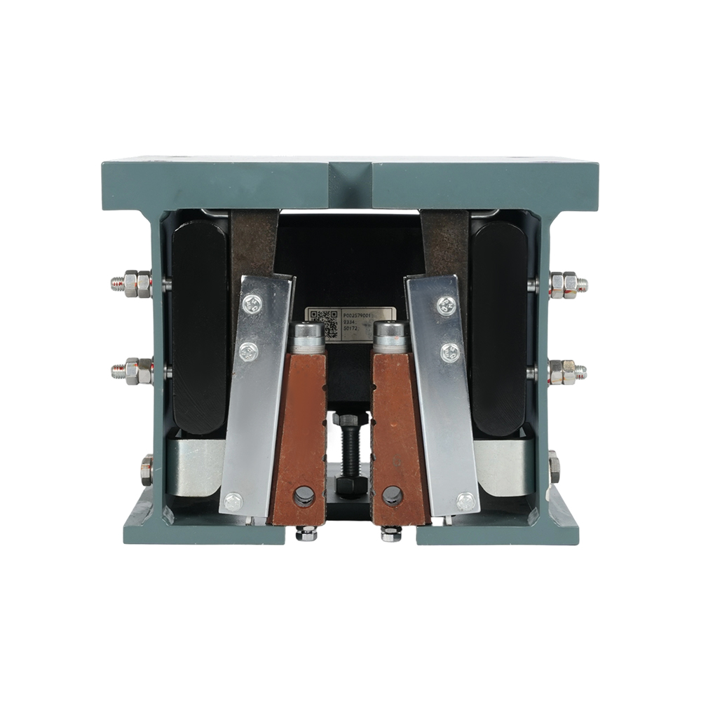
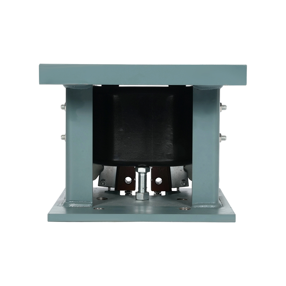
3.2 Safety Gear Housing and Jaw Assembly
The safety gear housing is a precision-machined structural casting (typically ductile iron or fabricated steel) that provides the geometric framework within which the jaw elements travel during engagement. Housing dimensional tolerances are critical: the clearance between the jaw element and the guide rail in the passive (non-engaged) state must be precisely controlled (typically 2–4 mm per side) to ensure reliable, consistent engagement without false contact during normal operation.
The jaw assembly components subject to the highest wear and stress during engagement are:
- Jaw elements (rollers or wedges): Manufactured from case-hardened alloy steel (typically 20CrMnTi or equivalent) with surface hardness of 58–62 HRC on contact faces. Must be replaced after any engagement event and inspected for dimensional conformity before reinstallation.
- Jaw guide surfaces (housing ramp or taper): The inclined surfaces within the housing that translate jaw element vertical displacement into horizontal clamping force. Surface finish and hardness of these ramp surfaces directly affect engagement force consistency and repeatability.
- Return springs: Compression springs that return the jaw elements to the passive position after the safety gear is reset. Spring fatigue or loss of preload over time can cause incomplete reset, leaving residual contact with the rail during normal operation.
3.3 Guide Rail Specification Requirements
The guide rail is the reaction structure against which the safety gear elevator applies its braking force. Rail specification must be matched to the safety gear type and the maximum static force the safety gear will apply to the rail during an engagement event. Key rail requirements include:
- Rail profile: T-section guide rails per EN 10056 or equivalent, with flange width and web thickness selected to withstand the safety gear clamping force without yielding. The rail running surface (flange face) must be maintained within flatness and surface roughness tolerances specified by the safety gear manufacturer.
- Rail material grade: S235 steel (minimum) for standard installations; S355 for high-speed or high-load applications where safety gear engagement forces are higher. Rail material yield strength directly limits the maximum clamping force the safety gear can apply without permanently deforming the rail.
- Rail jointing and fixing: Rail joint gaps must not exceed 0.5 mm (EN 81-20) to prevent jaw element impact at joint locations during engagement. Rail fixing bracket spacing and bracket stiffness must be sufficient to resist the lateral forces applied by the safety gear without rail deflection that would reduce effective clamping force.
3.4 Interaction with the Elevator Control System
While the safety gear elevator mechanism is entirely mechanical in its actuation and braking function, it interfaces with the elevator's electrical control system through safety circuit contacts that detect engagement. A safety gear engagement switch (typically a normally-closed contact in the elevator safety circuit) opens when the safety gear activates, cutting power to the drive and brake systems and preventing the elevator from attempting to resume operation until the safety gear has been manually reset and the circuit restored by a qualified technician. This electrical interlock prevents the drive motor from attempting to drive against an engaged safety gear—an event that could damage both the safety gear and the guide rails.
4. Elevator Safety Gear Inspection Checklist
4.1 Pre-Inspection Preparation
A structured safety gear elevator inspection checklist begins with pre-inspection preparation to ensure the inspection can be conducted safely and comprehensively. Required preparation steps include:
- Place the elevator out of service and secure with "Under Maintenance" signage at all landing doors.
- Isolate the main power supply and apply lockout/tagout (LOTO) per the site safety procedure.
- Review the elevator's technical documentation: original installation drawings, safety gear type-test certificate, previous inspection records, and any outstanding maintenance actions.
- Confirm that the inspection team includes at least one qualified elevator technician with documented competence in safety gear inspection per the applicable national standard.
- Prepare inspection tools: calibrated torque wrench, feeler gauges (0.05–5 mm range), surface roughness comparator, digital vernier caliper, inspection mirror and torch, and the safety gear manufacturer's maintenance manual.
4.2 Visual Inspection Points
The visual inspection phase of the safety gear elevator inspection checklist covers the following itemized checks:
- Housing integrity: Check for cracks, corrosion, or impact damage on the safety gear housing casting. Any crack in a safety-critical cast component requires immediate replacement—cracks cannot be welded or repaired.
- Jaw element condition: Inspect roller or wedge jaw elements for surface wear, pitting, scoring, or flat spots. Compare measured jaw dimensions against the manufacturer's wear limit table. Replace if wear exceeds the specified threshold.
- Rail running surface condition: Inspect the guide rail flange face in the safety gear engagement zone for scoring, corrosion pitting, or deformation from previous engagement events. Rail surface roughness should be within the manufacturer's specified range (typically Ra 1.6–6.3 µm).
- Passive clearance measurement: Use feeler gauges to measure the clearance between each jaw element and the rail flange face with the safety gear in the passive position. Compare against the specification (typically 2–4 mm). Clearance outside this range requires adjustment.
- Linkage and pull rod condition: Inspect the governor rope connection, pull rod, lever arm, and synchronization rod for corrosion, wear at pivot pins, elongated pin holes, and missing or damaged split pins or circlips.
- Return spring condition: Check springs for corrosion, visible fatigue cracks, and compare free length against the manufacturer's specification. Springs at or below minimum free length require replacement.
- Lubrication: Confirm that lubrication points are correctly lubricated per the manufacturer's specification. Note that rail running surfaces in the safety gear engagement zone must not be lubricated—oil contamination of the rail in this zone reduces friction coefficient and may prevent full safety gear engagement.
4.3 Functional Test Procedure
The functional test verifies that the safety gear elevator engages correctly under controlled conditions. This test must be conducted at the intervals specified by the applicable standard and whenever the safety gear has been disturbed or replaced:
- No-load drop test: With the car unloaded, manually trip the governor (or use the test trip device if provided) at the lowest available car speed. Confirm that both safety gear units engage simultaneously, the safety circuit opens, and the car stops without rotation or abnormal impact.
- Rated load drop test: With the car loaded to rated capacity, perform a governed overspeed test per the applicable standard. For progressive safety gear, measure the stopping distance and calculate the mean deceleration. Confirm the deceleration falls within the specified range (0.2g–1.0g per EN 81-20 Annex D).
- Engagement symmetry check: After each drop test, inspect both guide rails in the engagement zone for symmetric scoring or burnishing marks. Asymmetric marks indicate unequal jaw engagement, requiring linkage adjustment.
- Reset verification: After the drop test, reset the safety gear per the manufacturer's procedure, restore the governor, and confirm the safety circuit closes correctly. Run the elevator unloaded through full travel and confirm no abnormal noise, vibration, or control system faults.
4.4 Documentation and Compliance Recordkeeping
Every inspection conducted against the safety gear elevator inspection checklist must be fully documented to satisfy regulatory requirements and provide the audit trail required for insurance and liability purposes:
- Record the date, inspector identity, and qualification reference for each inspection.
- Document all measured values (jaw clearances, spring free lengths, drop test stopping distances, deceleration values) with pass/fail status against specification limits.
- Record all components replaced, including part numbers, batch numbers, and supplier documentation.
- Issue a written deficiency report for any non-conformance identified, with a defined corrective action timeline and responsible party.
- Retain all inspection records for a minimum period defined by the applicable national regulation (typically 5–10 years).
5. Elevator Safety Gear Maintenance and Testing
5.1 Routine Maintenance Schedule
Effective elevator safety gear maintenance and testing requires a structured, frequency-based maintenance program aligned with the applicable national standard and the safety gear manufacturer's recommendations. A typical maintenance schedule is:
| Frequency | Maintenance Activity | Standard Reference |
|---|---|---|
| Monthly | Visual check of governor rope condition and tension; safety circuit contact function test | EN 81-20 Clause 16.2; GB 7588 |
| Quarterly | Full visual inspection per checklist; passive clearance measurement; linkage lubrication | Manufacturer maintenance manual |
| Annually | Complete inspection checklist; governor trip speed verification; no-load drop test | EN 81-20 Clause 16.2; ASME A17.1 Rule 8.6 |
| Every 5 years | Full rated load drop test; jaw element dimensional inspection and replacement if at wear limit; spring replacement | EN 81-20 Annex D; national regulatory authority requirement |
| After any engagement event | Complete disassembly inspection; jaw element replacement; rail damage assessment; drop test before return to service | Mandatory — all standards |
5.2 Wear Indicators and Replacement Thresholds
Proactive component replacement based on measured wear indicators—rather than reactive replacement after failure—is the basis of effective elevator safety gear maintenance and testing programs. Key wear indicators and their replacement thresholds are:
- Jaw element contact face wear: Measure the jaw element contact face thickness or roller diameter against the manufacturer's new-part dimension. Replace when wear reaches 10–15% of the new-part dimension, or as specified in the manufacturer's wear limit table.
- Housing ramp surface wear: Inspect the inclined ramp surfaces within the housing for scoring or pitting. If ramp surface roughness exceeds Ra 3.2 µm or visible scoring depth exceeds 0.3 mm, the housing requires replacement—ramp surface reconditioning in the field is not an acceptable repair.
- Return spring free length: Measure free length against the nominal specification. Replace springs when free length has reduced by more than 5% of nominal, indicating fatigue-induced set.
- Pull rod and pivot pin wear: Measure pin diameter and pin hole bore. Replace when diametric clearance (pin-to-hole) exceeds 0.5 mm, which indicates wear that could cause delayed or asymmetric engagement timing.
- Governor rope diameter reduction: Replace governor rope when the measured diameter has reduced by more than 10% of the nominal diameter due to wire wear or corrosion.
5.3 Annual Load Test Requirements
Annual drop testing is a mandatory element of elevator safety gear maintenance and testing in most regulatory jurisdictions. The test must be witnessed by a qualified inspector and documented with measured results. Test protocol requirements per EN 81-20 Annex D include:
- Car loaded to rated capacity (100% of rated load).
- Car traveling downward at rated speed when governor is tripped (or car traveling at governor trip speed for overspeed simulation tests).
- Deceleration measured by accelerometer or calculated from stopping distance and entry speed. Must fall within 0.2g–1.0g for progressive safety gear.
- Both guide rails inspected post-test for symmetric engagement evidence and rail damage.
- Safety gear reset, drop test repeated minimum once more to confirm consistent performance.
5.4 Common Failure Modes and Corrective Actions
| Failure Mode | Root Cause | Corrective Action |
|---|---|---|
| Failure to engage on governor trip | Excessive passive clearance; linkage seizure; governor rope slack | Adjust passive clearance; inspect and lubricate linkage; adjust governor rope tension device |
| Asymmetric engagement (car tilt) | Unequal passive clearance; worn synchronization rod pivot pins | Re-adjust both units to equal clearance; replace worn pivot pins |
| Deceleration exceeds 1.0g (progressive type) | Spring preload set too high; jaw geometry worn beyond limit | Re-set spring preload per manufacturer specification; replace jaw elements |
| Deceleration below 0.2g (progressive type) | Spring preload set too low; oil contamination of rail and jaw contact surfaces | Re-set spring preload; degrease rail and jaw contact surfaces; identify lubrication source |
| Safety circuit does not open on engagement | Engagement switch misaligned or failed; wiring fault | Realign or replace engagement switch; inspect wiring continuity |
| Incomplete reset after engagement | Return spring fatigue; jaw element deformed after engagement | Replace return springs; inspect and replace jaw elements if deformed |
6. Regulatory Standards and Certification
6.1 EN 81-20/50 (Europe)
EN 81-20 (Safety rules for the construction and installation of lifts — Lifts for the transport of persons and goods) is the primary European standard governing safety gear elevator design, testing, and installation. The 2014 edition (with subsequent amendments) superseded the earlier EN 81-1 and EN 81-2 standards. Key EN 81-20 provisions for safety gear include:
- Clause 5.6: Complete safety gear system requirements including governor trip speed limits, stopping distance calculations, and deceleration limits.
- Annex D: Type test procedure for progressive safety gear, defining the test load, speed range, deceleration measurement methodology, and acceptance criteria.
- EN 81-50 (companion testing standard): Defines the type test procedures for individual safety components including safety gear, governors, and buffers. All safety gear elevator components installed in European markets must hold a valid EN 81-50 type-test certificate from a notified body.
6.2 GB 7588 (China)
GB 7588 is China's national standard for elevator safety, largely harmonized with EN 81-1/2 (and progressively with EN 81-20/50 through revision cycles). The current edition, GB 7588-2003 with Amendment 1 (2015), specifies safety gear elevator requirements substantially equivalent to the European framework. Products supplied to the Chinese domestic market require CCC (China Compulsory Certification) under the elevator product certification scheme administered by CNCA (Certification and Accreditation Administration of China). Safety gear is a mandatory CCC-certified component.
6.3 ASME A17.1 (North America)
ASME A17.1 (Safety Code for Elevators and Escalators) governs elevator installations in the United States and Canada. The A17.1 framework for safety gear elevator requirements is structured differently from the European EN 81 approach but achieves equivalent safety outcomes. Key provisions include Rule 2.17 (car safety devices) and Rule 8.6 (periodic testing requirements), which mandate annual no-load safety tests and five-year full-load tests with measured stopping distances for progressive safety gear. All safety components must be listed or approved by a nationally recognized testing laboratory (NRTL) such as UL, CSA, or ETL.


