
 English
 中文简体
中文简体 русский
 Español
 Deutsch


Engineering Selection Guide: Progressive vs. Instantaneous Safety Gear For Elevator Systems
Content
Mechanical Kinetic Energy Dissipation and Braking Principles
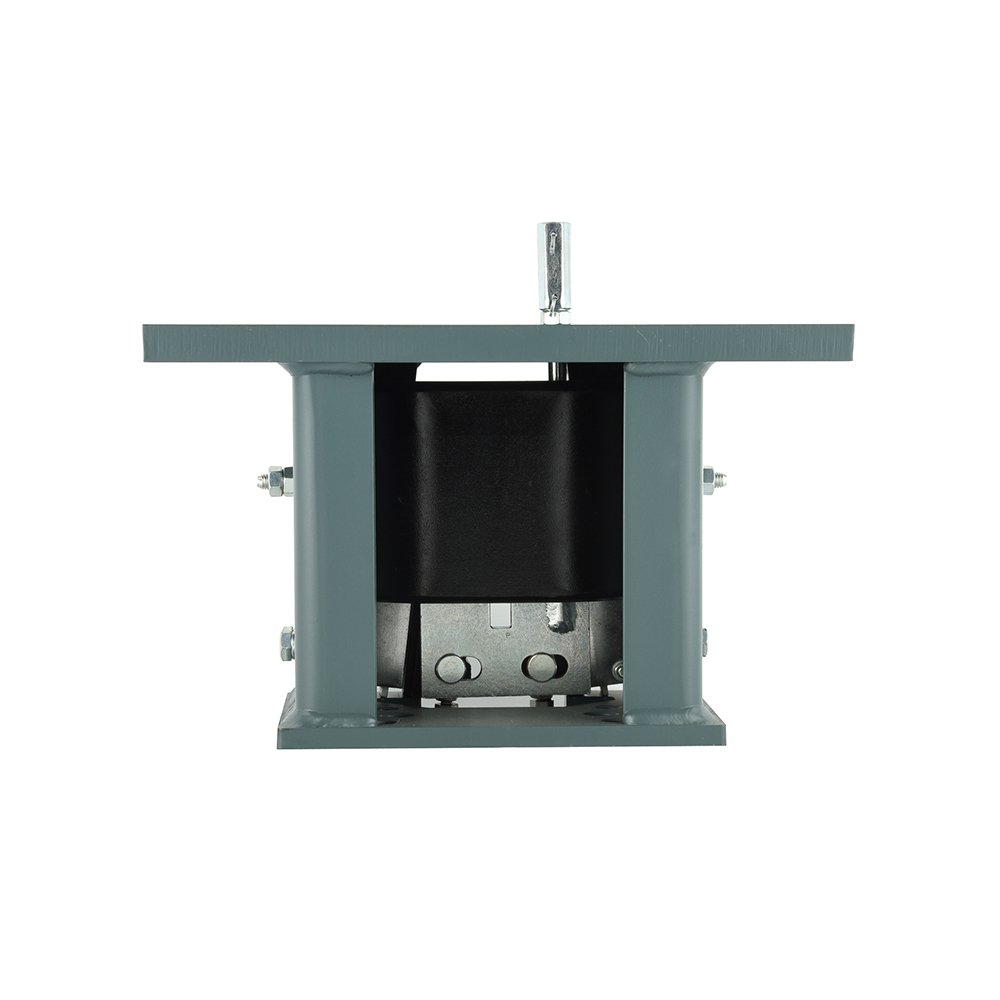
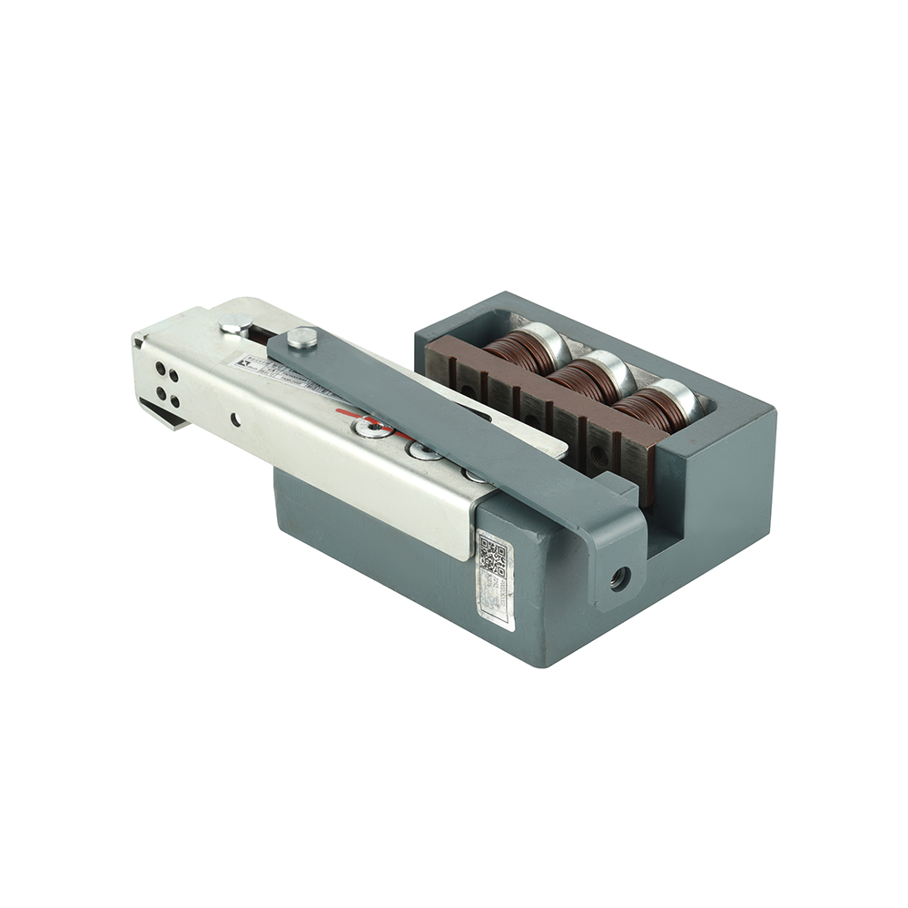
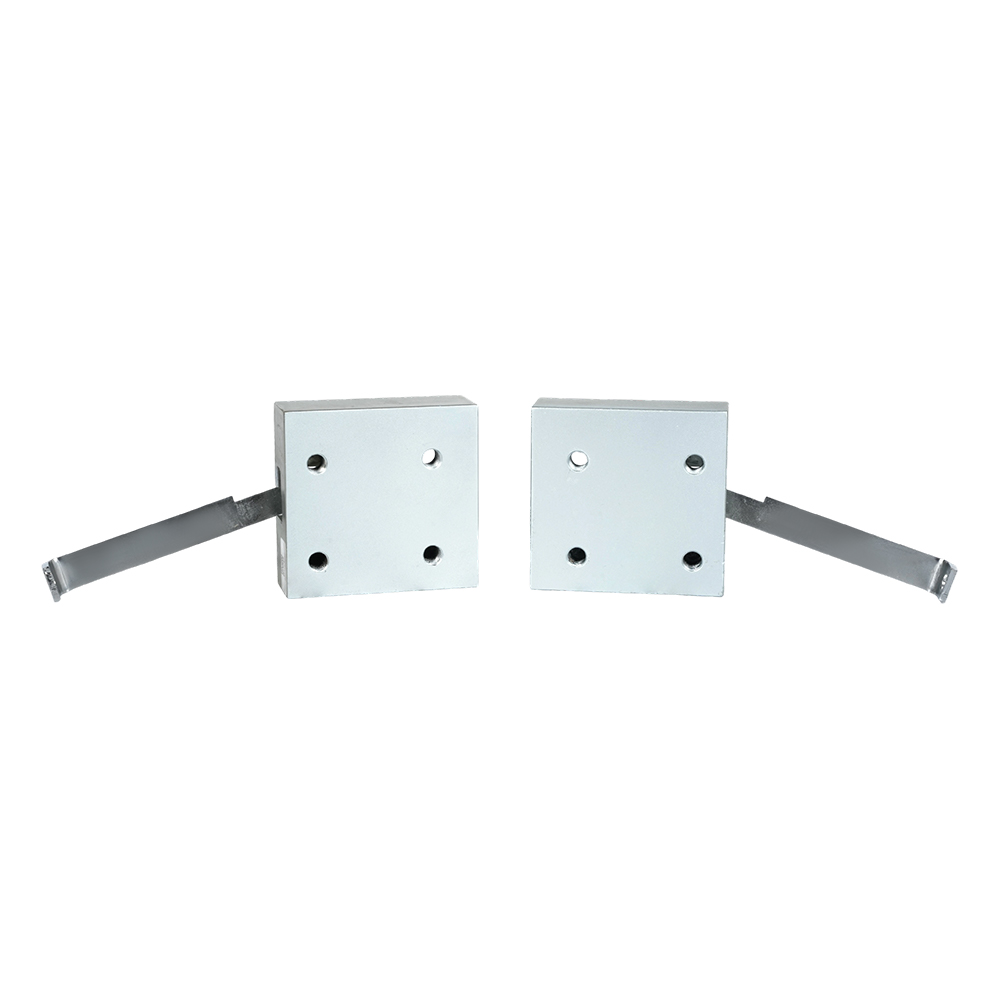
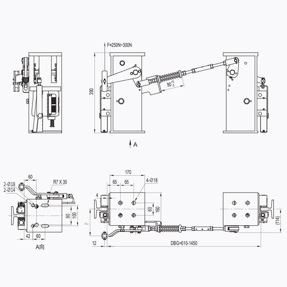
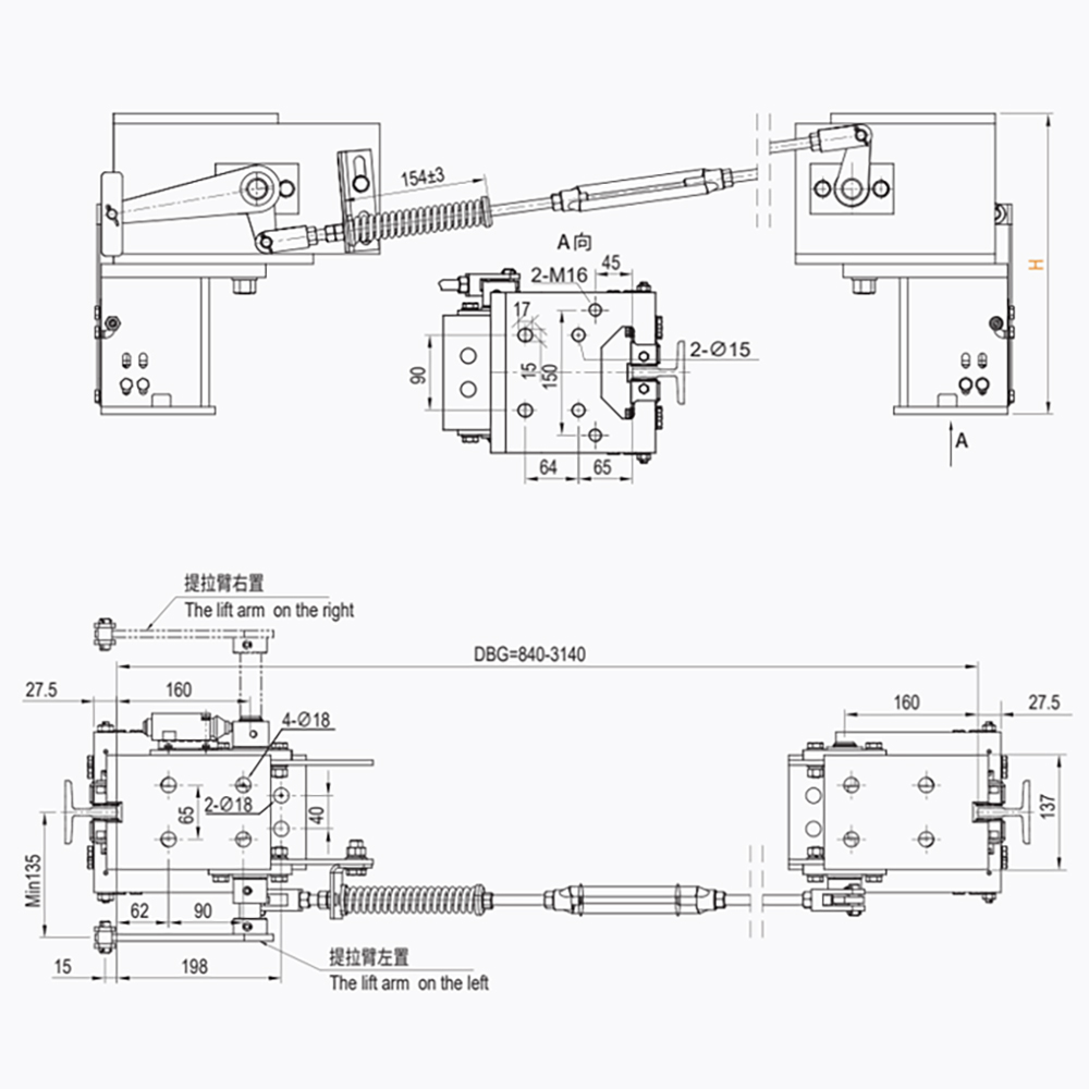
The operational safety of vertical transportation relies on the terminal braking capacity of the Safety Gear For Elevator. When evaluating How to choose between progressive and instantaneous Safety Gear For Elevator based on rated speed and load capacity?, engineers must prioritize the deceleration curve. Instantaneous safety gear locks onto the guide rails almost immediately through a wedge-type or roller-type mechanism, resulting in an abrupt stop. Conversely, progressive safety gear utilizes spring-loaded braking pads to allow for a controlled slide, dissipating kinetic energy through thermal friction. This distinction is vital for maintaining passenger safety during a free-fall or overspeed event.
- 1. Kinetic Energy Calculation: The selection process begins with calculating the total suspended mass (P+Q) and the tripping speed of the overspeed governor.
- 2. Braking Distance and Deceleration: Progressive models are engineered to maintain a deceleration rate between 0.2g and 1.0g, adhering to EN 81-20 safety requirements.
- 3. Mechanical response time of elevator safety gear: The interval between the overspeed governor cable pull and the full engagement of the wedges must be within milliseconds to prevent excessive velocity buildup.
- 4. Progressive vs instantaneous safety gear comparison: Instantaneous gear is restricted to low-speed applications (typically below 0.63 m/s) because the shock load at higher velocities would exceed the structural yield strength of the car frame and guide rails.
Technical Constraints of Rated Speed and Mass Capacity
The physical limitations of the guide rail material and the car frame structure dictate the appropriate Safety Gear For Elevator type. For high-speed traction elevators, the rated speed limits for elevator safety gear are the primary filter. If the rated speed exceeds 0.63 m/s, international standards such as ASME A17.1 and EN 81-50 mandate the use of progressive safety gear. This prevents the instantaneous locking force from causing permanent deformation of the T-section guide rails, which are usually manufactured from cold-drawn or machined carbon steel with specific surface hardness (Brinell scale).
- 1. Guide Rail Compatibility: The hardness of the safety gear wedges must be calibrated against the guide rail’s Ra surface finish to ensure a consistent friction coefficient.
- 2. Load Capacity (P+Q) Scaling: As the maximum load capacity for elevator safety gear increases, the clamping force must be distributed across a larger surface area to avoid localized material shearing.
- 3. System synchronization with overspeed governors: A dual-acting safety gear must ensure that both wedges engage simultaneously to prevent the car from tilting, which could lead to a catastrophic guide shoe failure.
- 4. Installation of safety gear on high-speed elevators: Progressive units require precise alignment with the guide rail center-line (within a tolerance of +/- 0.5 mm) to avoid parasitic drag during normal operation.
Friction Dynamics and Material Property Analysis
The braking force generated by a Safety Gear For Elevator is a function of the normal force exerted by the springs and the dynamic friction coefficient between the braking element and the rail. In emergency braking deceleration rates for elevators, the material of the braking pads—often a specialized alloy or ceramic-metallic composite—must maintain its tensile strength and friction profile even as temperatures at the interface exceed 400 degrees C during the sliding phase.
| Parameter | Instantaneous Safety Gear | Progressive Safety Gear |
| Max Rated Speed | Up to 0.63 m/s | Up to 10.0 m/s+ |
| Deceleration Control | Not Controlled (Abrupt) | Regulated (0.2g - 1.0g) |
| Thermal Dissipation | Minimal (Static Lock) | High (Sliding Friction) |
| Guide Rail Impact | High (Potential Deformation) | Controlled (Surface Wear Only) |
| Application Range | Small Freight / Residential | Commercial / High-Rise Traction |
- 1. Surface Pressure Tolerance: The clamping pads are designed to withstand specific surface pressures (N/mm2) to ensure the durability of elevator safety gear components over a 20-year lifecycle.
- 2. Safety gear for hydraulic elevators: Since hydraulic systems often operate at lower speeds, instantaneous gear is frequently used, provided the downward speed is governed.
- 3. Maintenance and reset procedures for safety gear: After a progressive gear trip, the wedges must be checked for material transfer (galling) and the springs must be verified for fatigue or loss of tension.
- 4. Corrosion resistance of safety gear housings: For installations in humid or coastal environments, housings should be galvanized or treated with epoxy coatings to meet ISO 12944 C4/C5 standards.
Integration with Electrical Safety Circuits
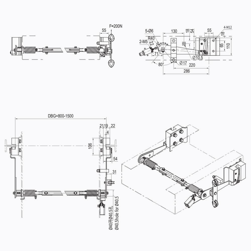
A mechanical trip of the Safety Gear For Elevator must be accompanied by an immediate electrical shutdown. The safety gear electrical interlock requirements stipulate that a safety switch must be activated before or at the moment of mechanical engagement. This ensures that the traction motor does not continue to rotate, which could lead to rope slip or damage to the drive sheave. Proper testing of elevator safety gear during commissioning includes a full-load overspeed test to verify both mechanical and electrical synchronization.
- 1. Redundancy and Reliability: The safety switch must be a "positive-break" type, ensuring that the circuit is physically forced open even if the contacts are welded.
- 2. Impact of friction coefficient on elevator safety: If the rail is over-lubricated or contaminated with dust, the braking force may drop below the required threshold, necessitating a higher spring tension setting.
- 3. How to calculate elevator safety gear braking force: Engineers use the formula F = (P+Q) * (g + a) / (2 * mu), where 'a' is the required deceleration and 'mu' is the dynamic friction coefficient.
Engineering FAQ
Q: Why is instantaneous safety gear prohibited on high-speed elevators?
A: At high speeds, the instantaneous stop generates a massive force (F=ma) that can buckle the car frame and cause severe spinal injuries to passengers due to the extreme deceleration.
Q: Can I use progressive safety gear on a low-speed elevator?
A: Yes. Progressive safety gear is technically superior and safer, though it is more expensive and requires more space for the spring housing.
Q: What is the significance of the Type Examination Certificate?
A: It is a document issued by a notified body (like TUV or Liftinstituut) proving that the specific safety gear model has passed physical drop tests and meets EN 81 or ASME standards.
Q: Do I need to replace the guide rails after the safety gear has tripped?
A: Usually, no. If the safety gear is progressive, you only need to file down any small burrs. For instantaneous gear, the rail must be inspected for permanent deformation or "gouging."
Q: How do I adjust the braking force on a progressive safety gear?
A: Adjustment is typically done by modifying the compression of the disc springs (Belleville washers) according to the manufacturer’s load chart.
Technical References
- EN 81-20: Safety rules for the construction and installation of lifts.
- ASME A17.1: Safety Code for Elevators and Escalators.
- ISO 8100-1: Lifts for the transport of persons and goods.