
 English
 中文简体
 русский
 Español
 Deutsch



Elevator Safety Gear Linkage Device Mechanism: Design, Tolerance and Failure Data
Content
- 1 How the Elevator Safety Gear Linkage Device Sequences Five Actuation Stages
- 2 Synchronization Tolerance in an Elevator Safety Gear Linkage Device
- 3 Field Data: What Actually Seizes a Linkage Device
- 4 Selection, Installation and Reset: A Practical Check Sequence
- 5 Frequently Asked Questions About Elevator Safety Gear Linkage Devices
An eight-year-old machine-room-less passenger lift in a coastal apartment block failed its annual inspection for one reason: the safety gear on the left guide rail gripped the rail, while the safety gear on the right arrived late.
The car stopped, but the rail carried roughly 400 mm of single-sided scoring, and peak deceleration was high enough to unbalance a standing passenger. The part that failed was not the safety gear. It was the elevator safety gear linkage device, a compact steel assembly whose pivot bushing had seized after years of salt-air corrosion and skipped lubrication.
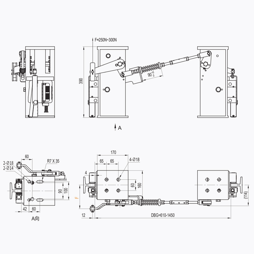
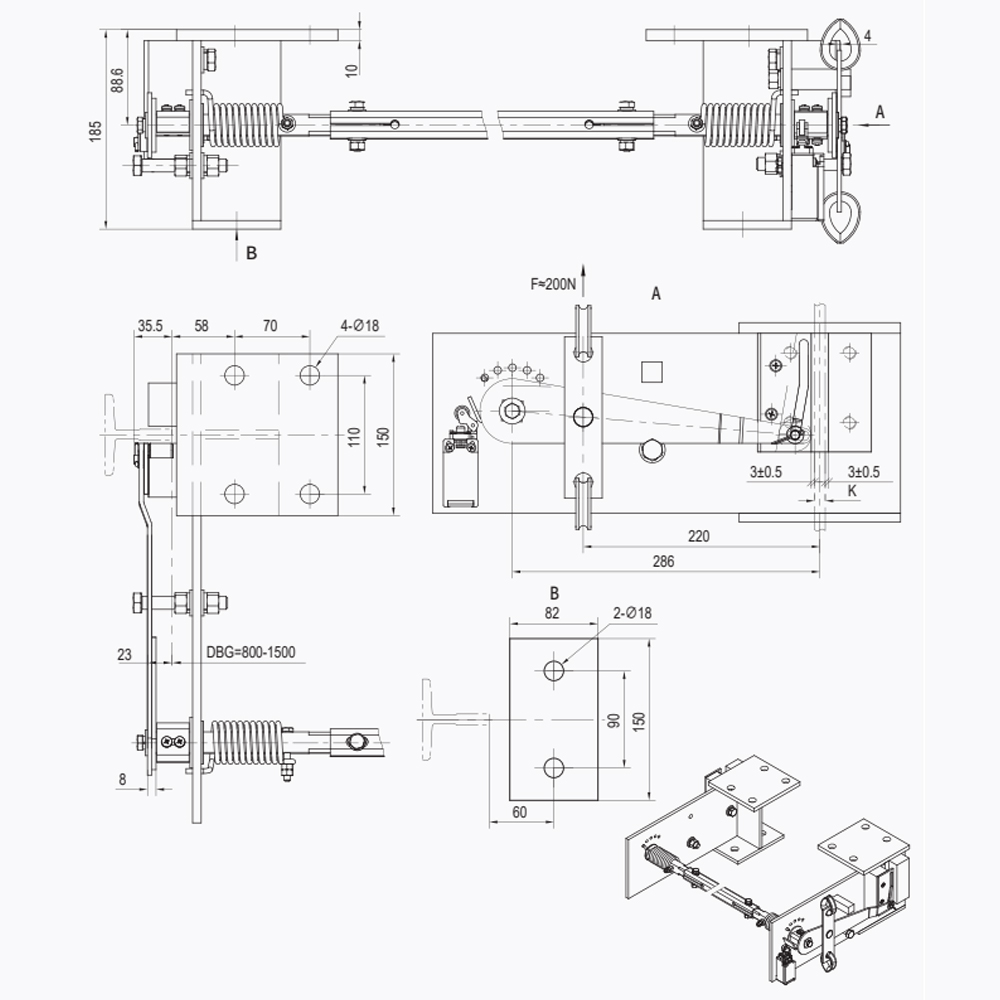
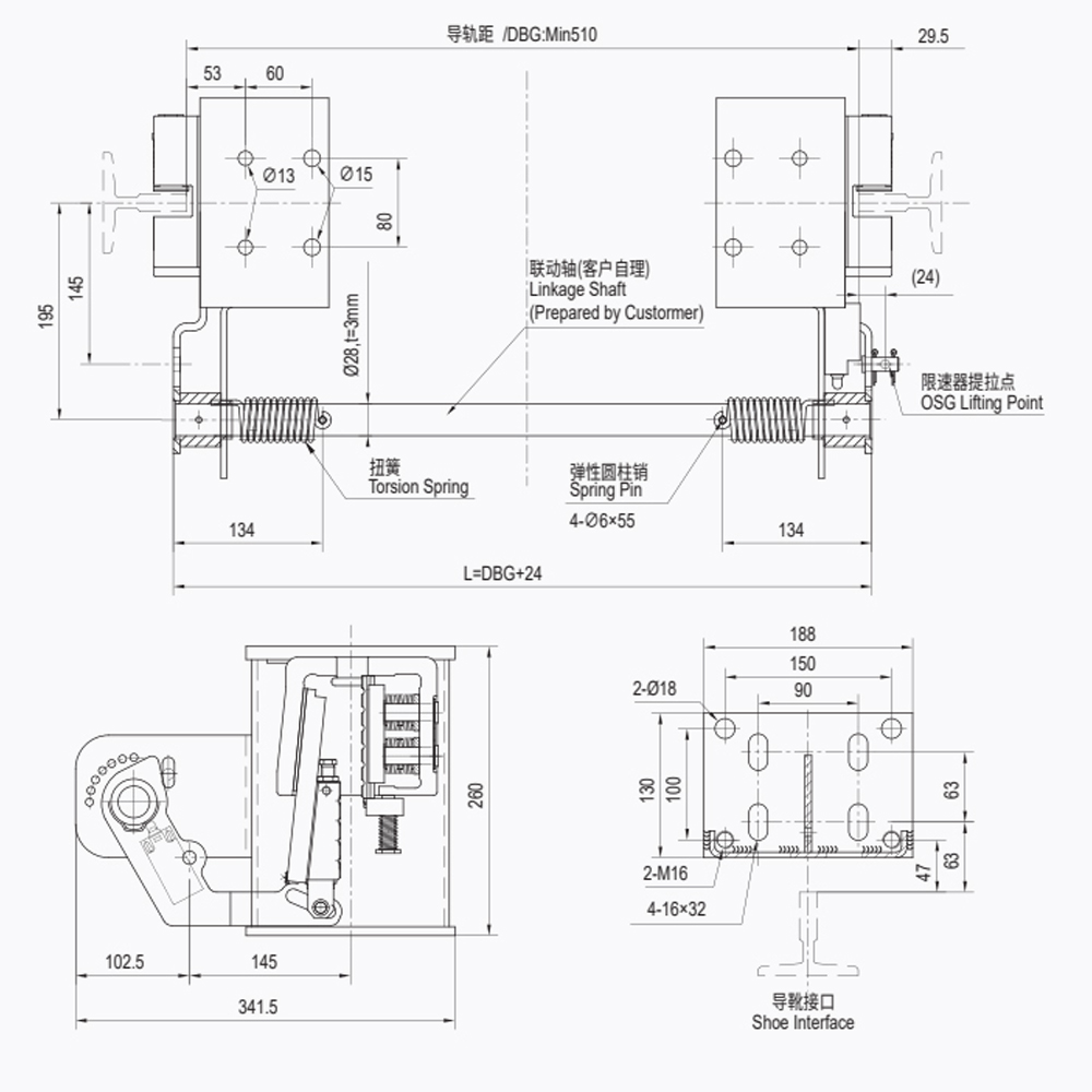
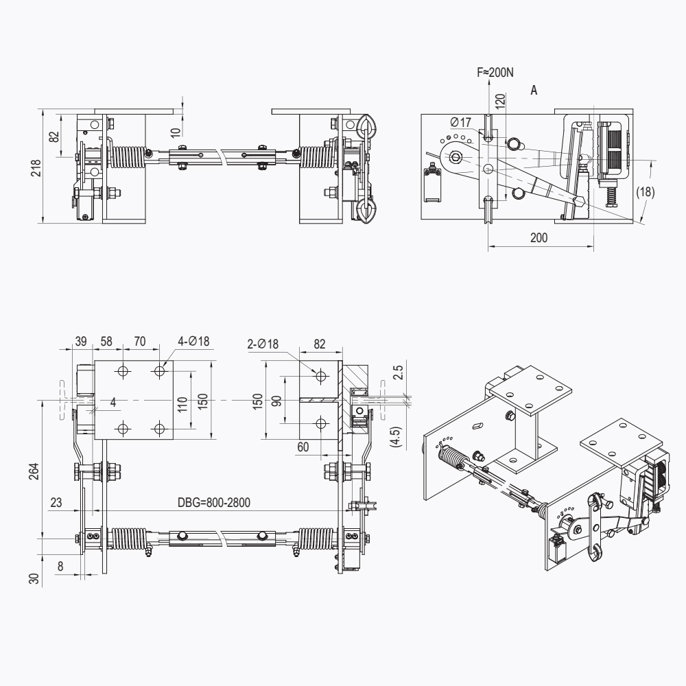
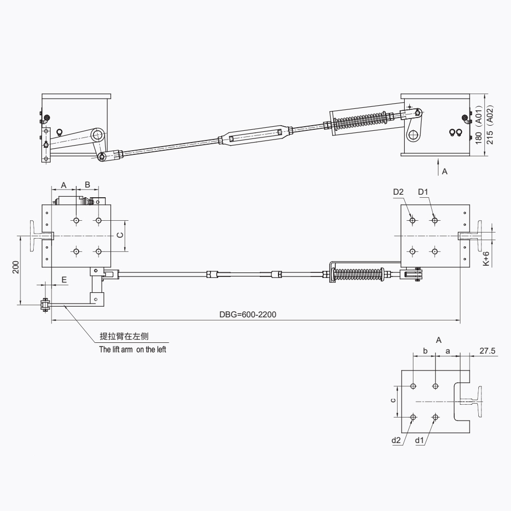
Definition: an elevator safety gear linkage device is the mechanical transmission that converts one upward pull of the overspeed governor rope into two simultaneous lifting actions, one on each safety gear block, so both wedges engage their guide rails at the same instant.
That simultaneity is the entire job. When one wedge bites before the other, the car yaws between the guide rails, a single rail absorbs the whole braking force, and the deceleration curve spikes. Rail scoring and passenger injury risk both rise during what should be the safest event in the shaft.
Shanghai Liftech Elevator Accessories Co., Ltd., which has manufactured elevator safety components since 2004, treats the linkage as a matched mechanical system rather than a loose spare part: transfer rod, rocker, springs, rollers and reset hardware are assembled and tested as one unit.
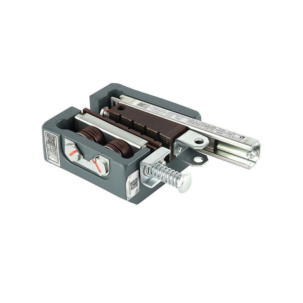
 LSD01 Elevator Safety Gear Linkage DeviceFive-stage linkage assembly rapidly engages the safety clamp on overspeed, with matched components and LSG01 safety gear options.View Product →
How the Elevator Safety Gear Linkage Device Sequences Five Actuation Stages
Answer first: the mechanism runs through five stages, and each stage depends on the previous one staying inside its tolerance.
- Governor trip. The overspeed governor closes its jaws on the governor rope once car speed passes the tripping threshold. For a 1.0 m/s lift, standards place that threshold between 1.15 and 1.5 times rated speed.
- Rope tension transfer. The rope stops with the car, so rising tension, typically a few hundred newtons, travels down the rope toward the car frame.
- Linkage lift. The linkage device converts that linear pull into a vertical lift of both wedge blocks. A transfer rod, often called a synchronization rod, keeps the left and right blocks moving together.
- Wedge engagement. Each wedge rides up between the guide rail and the safety gear housing. Friction self-energizes the grip, so the harder the car pulls, the harder the wedge bites.
- Braking and cut. The wedges clamp, average deceleration settles between 0.2 g and 1.0 g, and a switch cuts the motor supply while signaling the controller.
Rope condition matters as much as the linkage itself. A governor rope that hangs too loose delays tension transfer by tens of milliseconds; a rope that is too tight loads the tension device and invites nuisance trips. The function types and governor connection of safety linkage systems are worth reviewing whenever a linkage has to be matched to a specific governor family or rope diameter.
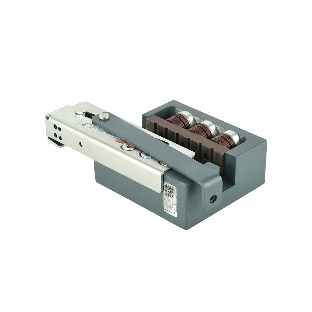
 LSD07 Governor-Triggered Safety Gear SystemDual-link safety gear system for governor-triggered stopping, offered with LSG06 and LSG06B specifications for overspeed protection.View Product →
Synchronization Tolerance in an Elevator Safety Gear Linkage Device
Answer first: both safety gear blocks should reach rail contact within about 1 mm of each other in lift travel, and a difference of 3 mm or more means the geometry has been lost.
Rigid transfer rods do not self-correct. Pin wear, a bent rod, a deformed mounting bracket or a partially seized roller all appear as a travel difference between the two ends. Measure lift travel at each block with a dial indicator during a static trip, then compare reset spring free length and roller clearance against the drawing.
A linkage that reaches one block 40 ms later than the other can place the full braking load on a single wedge and a single guide rail.
| Arrangement | Typical trip latency | Adjustment sensitivity | Typical application |
| Rigid transfer rod | 10 to 20 ms | High, matched travel within 1 mm | Passenger lifts from 0.63 to 2.5 m/s |
| Rope or cable synchronized | 25 to 50 ms including cable stretch | Moderate, partly self-equalizing | Retrofit and split-mounting layouts |
| Electrically actuated | Under 10 ms after signal | Low, timing set by the controller | UCMP systems and high-speed machine-room-less lifts |
Latency is the second variable after travel. A rigid rod gives the fastest and most predictable engagement on standard passenger lifts, while a rope-synchronized linkage forgives imperfect mounting geometry on retrofit projects. Electrically actuated triggers buy speed, but they shift the tolerance question from the linkage to the controller logic and its sensor chain, which is a different set of failure modes.
Field Data: What Actually Seizes a Linkage Device
Answer first: corrosion and dry pivots cause most linkage faults, not mechanical overload.
Humidity is the common thread behind those numbers. Machine-room-less shafts in coastal or tropical locations see condensation on cold steel, and a bushing that loses its grease film in year two is often a seized pivot by year six. Stainless pins, bronze bushings and a sealed roller set change that timeline more than a heavier rod does. A lubrication interval of 12 months, checked together with governor rope tension, keeps travel difference inside 1 mm for the service life of the lift.
Selection, Installation and Reset: A Practical Check Sequence
Answer first: buy the linkage as a matched assembly, prove it on the bench, then prove it again in the shaft before handover.
- Travel difference between left and right blocks within 1 mm at full lift
- Reset spring returns both wedges with no stick-slip
- Roller clearance and wedge contact angle match the drawing
- Humidity or salt-spray cycle on pins and bushings without seizing
- Governor rope tension inside the tension device working range
- Both wedges aligned to the same rail plane within 1 mm
- Trip test at rated speed with a recorded deceleration curve
- Manual release reachable and operable from the car top
Reset deserves its own line in the checklist. After a trip, the wedges must release and return fully to their parking position, because a linkage that restarts from a partly engaged state will bite earlier and harder on the next trip. A dedicated lift safety gear release device, matched to the same rod geometry, shortens that job to a single controlled operation and removes the temptation to lever a wedge free with a screwdriver.
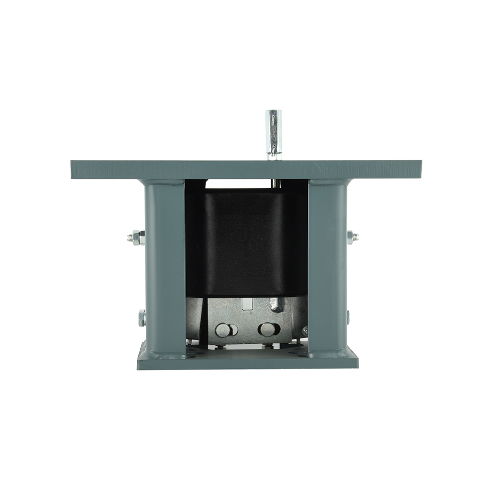
 LSD12 Lift Safety Gear Release DeviceDedicated release device that resets wedges fully and links both safety clamps, matched to LSG03 progressive safety gear.View Product →
Frequently Asked Questions About Elevator Safety Gear Linkage Devices
What is the difference between a safety gear linkage device and the safety gear itself?
The safety gear is the clamping block that grips the guide rail. The linkage device is the transmission that lifts both blocks at once when the overspeed governor trips. One grips; the other decides when and how evenly the grip happens.
How often should a linkage device be inspected or lubricated?
Twelve months is workable for most passenger lifts, and six months for coastal, humid or high-cycle installations. The inspection should record travel difference between the two blocks, roller clearance, reset spring condition and governor rope tension, not just a visual check for grease.
Can a linkage device be retrofitted to an older elevator?
Yes, if the safety gear, governor and guide rail geometry are documented first. Retrofits usually pair a rope-synchronized linkage with existing instantaneous safety gear on low-speed lifts, while progressive safety gear above 0.63 m/s needs a rigid transfer rod matched to the block mounting.
Why do the left and right safety gears sometimes engage at different times?
Three causes dominate: a dry or corroded pivot that adds friction on one side, a bent transfer rod that changes effective length, and unequal roller clearance at the two blocks. All three are measurable, and all three show up as a travel difference larger than 1 mm during a static trip test.