
 English
 中文简体
中文简体 русский
 Español
 Deutsch


Elevator Safety Device Guide: How Overspeed Governors, Safety Gear and Buffers Work
Content
- 1 Every Elevator Safety Device Has One Defined Role
- 2 Overspeed Governor: The Device That Decides When to Stop
- 3 Safety Gear: Progressive vs Instantaneous Stopping Behavior
- 4 Oil Buffer: The Last Device in the Energy-Absorption Path
- 5 Rope Brake and Linkage Device: Two Components that Make the Chain Complete
- 6 How to Select and Verify Elevator Safety Devices for Your Project
- 7 FAQ: Elevator Safety Device Questions
A 3,000 kg freight elevator overspeeds three floors above the pit, and the car has less than half a second before something must physically stop it. The first device to act is the overspeed governor, which has to decide whether to fire. That decision, and the chain of devices it sets in motion, is the practical meaning of an elevator safety device system.
An elevator safety device system is the set of speed-sensing, braking and energy-absorbing components that detect abnormal movement and stop the car within a defined stopping distance. For a traction elevator, this normally means the overspeed governor, safety gear, safety linkage device, oil buffer and, in some configurations, a rope brake.
For procurement engineers and elevator manufacturers, the practical question is not which device to buy, but how these devices match each other in speed, trigger force and stroke. The following sections explain each link in the chain, the parameters that drive selection, and the compliance checks that make or break an installation.
Safety device definition: The coordinated combination of speed-sensing, braking and energy-absorbing components that protects passengers and equipment when an elevator exceeds its rated operating envelope.
Every Elevator Safety Device Has One Defined Role
Each elevator safety device has a single defined role in the chain, and the system only works when they trigger in the right sequence.
The five-part chain is standard for most traction elevators. Each component is type-tested on its own, but it is the combination that provides the certified safety function.
- Overspeed governor: senses car speed and initiates the trip.
- Safety linkage device: transmits the governor command to the safety gear.
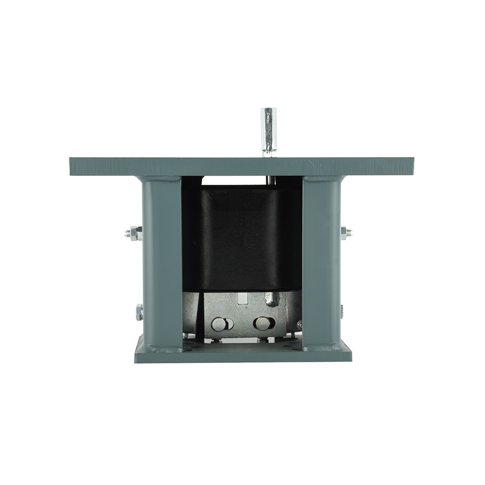
- Safety gear: clamps the guide rails to stop the car.
- Rope brake: grips the suspension ropes for uncontrolled movement protection.
- Oil buffer: absorbs residual energy at the pit bottom.
A governor that trips at the wrong threshold, or a linkage device with too much mechanical play, prevents the safety gear from engaging within the allowable travel distance.
Overspeed Governor: The Device That Decides When to Stop
The overspeed governor is the detection device in the chain: it triggers the elevator safety device sequence at a preset overspeed threshold, normally 115% of rated speed.
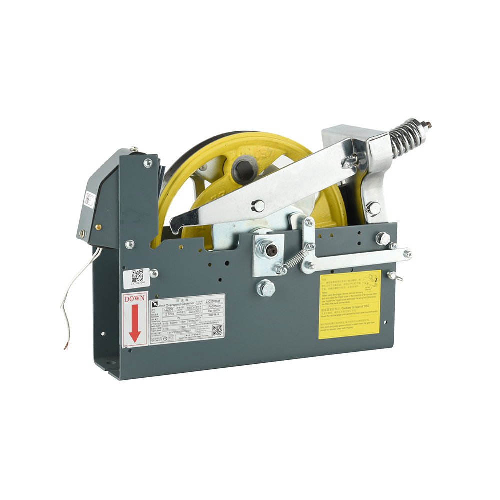
The governor measures car speed through a grooved wheel and a rope attached to the car. A centrifugal mechanism sits inside the rotating body. When speed exceeds the preset threshold, the mechanism releases the locking pawl and activates two separate outputs: an electrical switch that cuts power to the drive, and a mechanical lever that pulls the safety linkage device.
In most modern designs, the electrical trip happens first. If the car continues to accelerate for mechanical reasons, the device goes to full mechanical lockup.
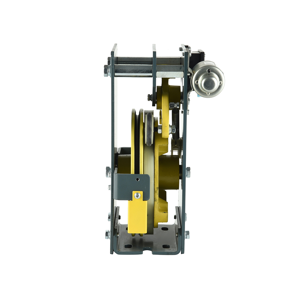 Bi-Directional Overspeed Governor with Remote Trigger and ResetThis cam-type governor offers mechanical bidirectional triggering and remote operation, suitable for machine-room-less elevators. It complies with GB7588 and EN81, supports 220VAC or 24VDC, and features a dual-contact switch.View Product →
Precision overspeed governor definition: A mechanical speed-sensing device that compares the actual car or counterweight speed against a preset threshold and initiates the safety braking sequence.
Safety Gear: Progressive vs Instantaneous Stopping Behavior
Use progressive safety gear for higher-speed passenger and freight elevators, and instantaneous safety gear for low-speed villa or small goods lifts.
Progressive safety gear is designed for rated speeds above 1.75 m/s in most codes. It uses spring-loaded rollers or wedge elements that apply gradually increasing clamping force, producing a controlled deceleration over 200 to 600 mm of travel. The stopping distance is calculated from the kinetic energy of the car and the permitted deceleration limits.
Instantaneous safety gear locks almost instantly. A wedge digs into the guide rail and the car stops in 50 to 100 mm. This creates a much sharper deceleration, which is only acceptable for low-speed applications such as home elevators and villa lifts.
Progressive safety gear
- Rated speed: 1.0 to 4.0 m/s
- Stopping distance: 200 to 600 mm
- Deceleration: controlled and gradual
- Best for: passenger, freight and high-rise
Instantaneous safety gear
- Rated speed: 0.4 to 0.63 m/s
- Stopping distance: 50 to 100 mm
- Deceleration: abrupt and sharp
- Best for: villa, home and small goods lifts
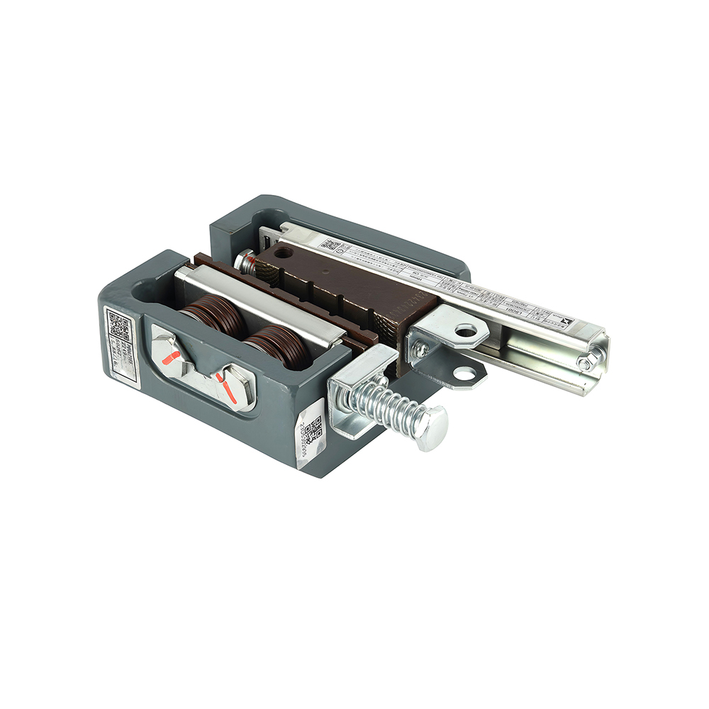
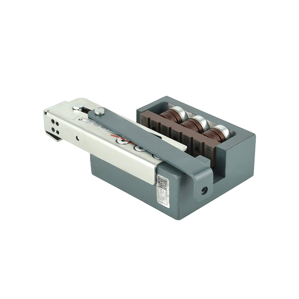
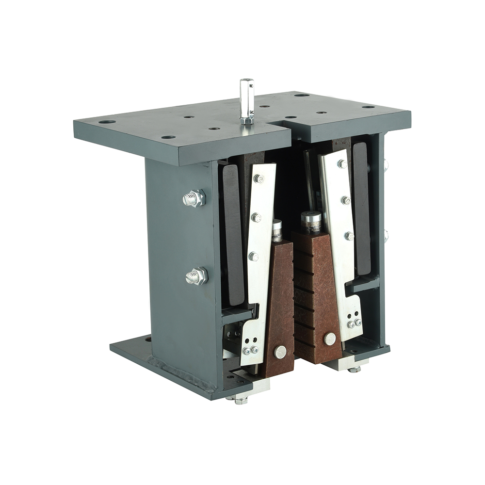 Heavy-Duty Freight Elevator Safety Gear for High Loads and SpeedsDesigned for systems up to 30 tons and speeds up to 2 m/s, this safety gear uses long-life friction materials and a U-shaped leaf spring for balanced braking, ensuring reliable performance in demanding freight applications.View Product →
| Attribute | Progressive safety gear | Instantaneous safety gear |
| Typical rated speed | 1.0 to 4.0 m/s | 0.4 to 0.63 m/s |
| Stopping distance | 200 to 600 mm | 50 to 100 mm |
| Clamping force | Gradual, spring-loaded | Immediate, wedge-driven |
| Passenger comfort | Higher | Lower |
| Common applications | Passenger and freight | Villa and home |
For a more detailed technical review of working principles and maintenance requirements, see our elevator safety gear guide.
The gradual clamping of a progressive safety gear is not a luxury. It is what keeps passenger deceleration within the limits required by code.
Oil Buffer: The Last Device in the Energy-Absorption Path
The oil buffer, also called the hydraulic buffer, is the final elevator safety device that absorbs the car's remaining kinetic energy at the bottom of the shaft.
The buffer is installed in the pit below the car and counterweight. When the car reaches the pit at overspeed, the buffer piston enters the fluid chamber and pushes oil through a calibrated orifice. The orifice geometry controls the rate of deceleration, converting the car's kinetic energy into heat.
Buffer stroke is the critical selection parameter. Common stroke classes are 100 mm, 150 mm, 175 mm, 200 mm and 250 mm, each corresponding to a specific impact speed capacity. Capacity, on the other hand, is defined by the total mass - rated load plus empty car weight - that the buffer must absorb.
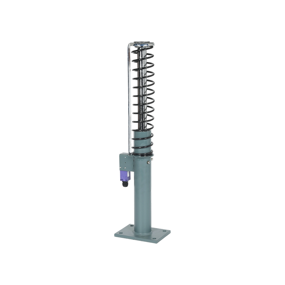 Hydraulic Oil Buffer for Smooth Elevator Energy DissipationThis oil buffer absorbs impact energy through hydraulic damping, converting kinetic energy into heat for smooth deceleration without rebound. Compact and low-maintenance, it suits residential and light-duty elevators.View Product →
Stroke and capacity are linked. Increase the rated speed, and you need a longer stroke so the car can be decelerated without bottoming out.
Rope Brake and Linkage Device: Two Components that Make the Chain Complete
The rope brake and the safety linkage device cover uncontrolled car movement and transmit the governor command - two functions that are easy to overlook in the selection process.
A rope brake, also referred to as a lift rope gripper or rope clamp, grips the suspension ropes instead of the guide rails. It is used in machine-roomless elevator systems to protect against unintended car movement when the doors are open, commonly called UCMP.
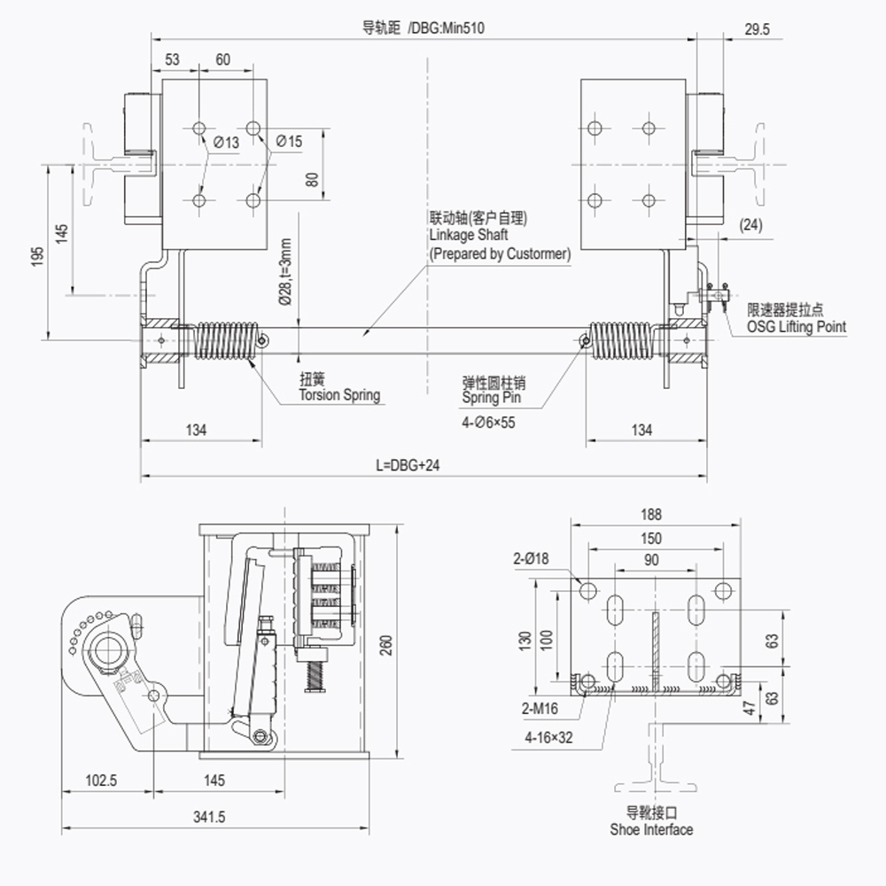
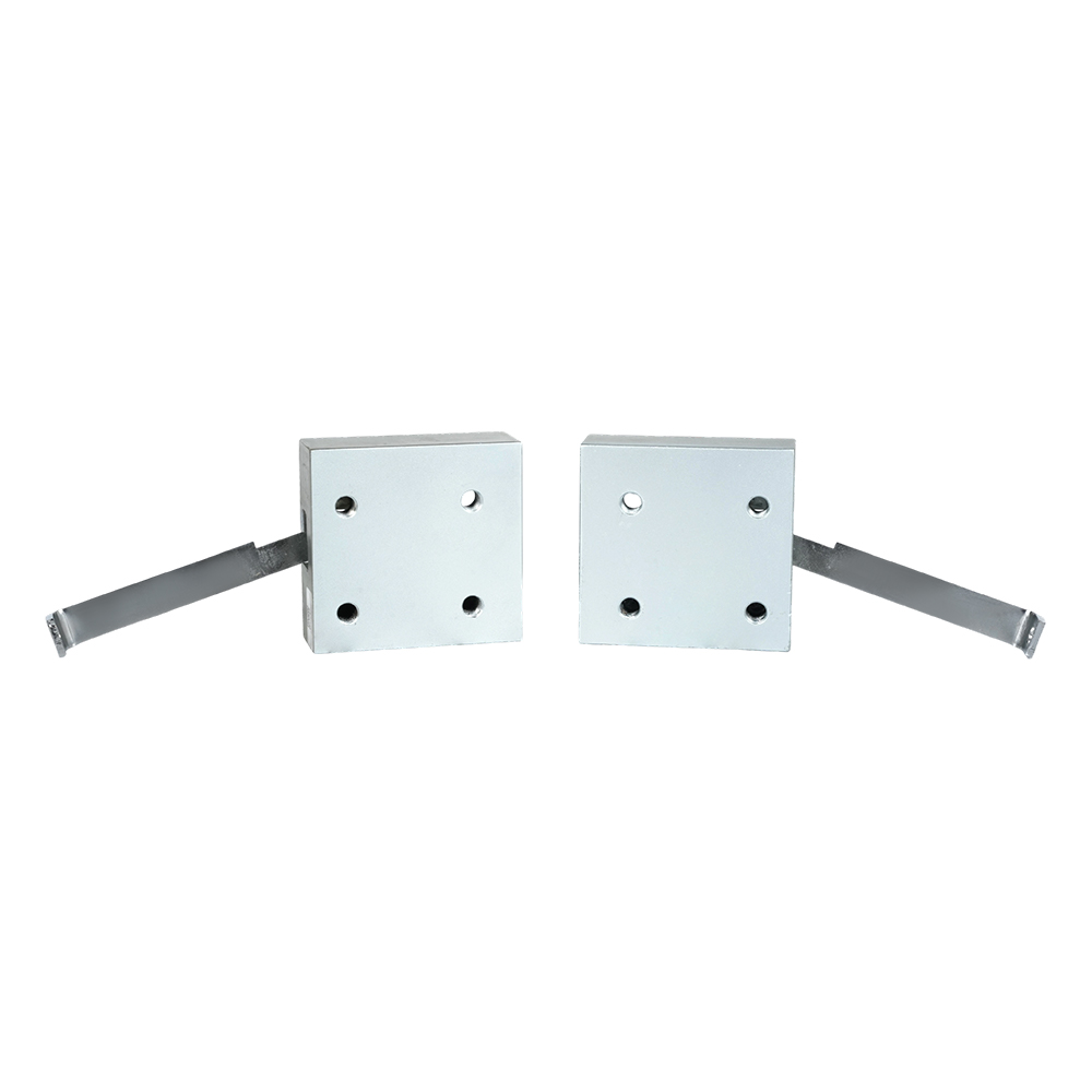
The safety linkage device is the mechanical member that connects the governor's trigger to the safety gear. When the governor fires, the linkage pulls the operating lever on the safety gear, which releases the clamping elements. Several linkage models exist with different lever ratios and release directions.
- Governor trigger stroke: check the mechanical travel available in the linkage.
- Release direction: match the linkage to the governor's pull direction.
- UCMP protection: confirm the rope brake reacts within the allowed door-zone gap.
- Mounting length: verify the linkage fits the car frame to safety gear distance.
How to Select and Verify Elevator Safety Devices for Your Project
Start with rated speed, rated load and shaft layout, then verify the device chain against the applicable code - EN 81-20/50, ASME A17.1 or GB/T 7588.
The selection process is driven by five inputs:
- Rated speed: determines the safety gear type and the governor threshold.
- Rated load and car mass: defines the buffer capacity.
- Shaft depth: limits the available buffer stroke.
- Elevator type: passenger, freight, villa or machine-roomless.
- Applicable code: sets the type-test and marking requirements.
Shanghai Liftech Elevator Accessories Co., Ltd., operating under the Liftech brand, supplies the governor, safety gear, oil buffer and rope brake series shown in the selection matrix below.
| Application | Governor model | Safety gear type | Buffer class |
| Villa / home | LOG06 / LOG07 | Instantaneous LSG02 | Short stroke LHB-E |
| Freight | LOG01 / LOG02 | Progressive LSG17 | Long stroke LHB-D |
| High-rise | LOG20 | Progressive LSG10 / LSG22 | Long stroke LHB-D |
| UCMP retrofit | LUC03 | Progressive plus linkage | Depends on car mass |
Before approving a supplier, verify the device chain against the EN 81-20/50 compliance guidance and confirm the type-test certificates.
Type-test certificate is the mandatory acceptance document for the safety gear, governor and buffer. Without it, the device cannot be used in a new installation or a modernization project in most regulated markets.
FAQ: Elevator Safety Device Questions
What is the main difference between a safety gear and a rope brake?
The safety gear clamps the guide rails, while the rope brake clamps the suspension ropes. The safety gear is normally triggered by the overspeed governor, whereas a rope brake is used for unintended car movement protection in machine-roomless systems.
At what speed does the overspeed governor trigger?
Most codes require the electrical trip at 115% of rated speed. The mechanical trip happens at 120 to 140%, depending on the rated speed and the applicable standard.
When should I choose progressive rather than instantaneous safety gear?
Choose progressive for rated speeds above about 1 m/s, and especially above 1.75 m/s, where controlled deceleration is required. Choose instantaneous for low-speed applications below 0.63 m/s, such as villa and home lifts.
How can I verify that a safety device is compliant?
Check the type-test certificate, the device marking, the governor trigger speed, the safety gear rated speed and stopping distance, and the buffer stroke and capacity against the project data.
Fastest compliance check: compare the nameplate data on the governor, safety gear and buffer with the project's rated speed, load and stroke values.