
 English
 中文简体
中文简体 русский
 Español
 Deutsch


Elevator Safety Gear Linkage Device: Mechanism, Function & Sourcing Guide
Content
- 1 Why the Linkage Device Is the Decision Point in the Safety Chain
- 2 Anatomy of a Safety Gear Linkage Mechanism
- 3 Common Linkage Configurations and When to Use Them
- 4 Design Factors That Decide Triggering Reliability
- 5 What to Verify Before Sourcing a Linkage Device
- 6 Standards and Compliance Considerations
- 7 Conclusion: The Linkage Is Where Safety Is Confirmed
On a lift acceptance test, the dramatic moment is when the car drops and the safety gear bites the guide rail. But the decisive work happens a fraction of a second earlier, inside the interface between the overspeed governor and the safety gear: the governor rope locks, the linkage mechanism converts that arrest into an upward lifting motion, and the wedge sets on both sides of the car frame move into the rail at the same instant. If the elevator safety gear linkage device is poorly matched, loosely adjusted, or built with excessive tolerance, even a correctly rated safety clamp will fail to stop the car as designed.
That is why the linkage deserves more attention than its simple appearance suggests. Below, we explain how the mechanism works, which components define its reliability, and what engineers and buyers should verify before installing or sourcing one.
Why the Linkage Device Is the Decision Point in the Safety Chain
The overspeed governor is the sensor; the safety gear is the actuator. The linkage device sits between them and must do three jobs at once: transmit the trigger force, synchronize both wedge sets, and enable a clean reset after the trip. If any one of these fails, the elevator can fall until the buffer engages, which is why the linkage is treated as part of the safety gear system rather than a simple mounting bracket.
- Force transmission – the governor rope arrest must be strong enough to move the wedge lifting mechanism against friction and spring force.
- Synchronization – one rod or shaft must push both safety gears into the rail without measurable delay between sides.
- Reversibility – after the car is raised and the governor rope released, the linkage must return to its neutral position unaided or with light spring assistance.
Most field complaints about safety gear operation – one-sided rail marks, wedges that do not return fully after a test, or a trip that requires too much pull on the governor rope – trace back to the linkage and its adjustment, not to the wedge or the rail itself.
Anatomy of a Safety Gear Linkage Mechanism
The Components That Make Up the Mechanism
A typical linkage assembly for a progressive safety gear includes the following:
- A governor rope connection (fork or clamped eye) that interfaces the governor rope with a lever.
- A lever or bell crank that multiplies rope movement and changes its direction.
- A connecting rod that runs across the car frame and carries motion to both sides.
- Wedge lifting arms on each safety gear that raise the wedge sets into contact with the guide rail.
- A limit bolt or stop that defines the full engagement position.
- Return springs (on many models) that pull the mechanism back to the released position.
The layout looks simple, but each component has a strict dimensional role. A lever with even a small amount of free play delays one side of the car by a few millimeters of stroke – enough to tilt the car during emergency braking.
How the Trigger Sequence Works
A typical trip runs through the following steps:
- The overspeed governor actuates and locks its rope.
- The car continues to move; the locked rope pulls the linkage lever.
- The lever rotates, converting rope tension into an upward lifting motion.
- Lifting arms push the wedge sets up between the guide rail and the safety gear body.
- The limit bolt stops further stroke, and the wedges remain clamped against the rail.
- After clearance, the car is raised, the governor rope is released, and the return springs reset the wedges.
On a machine-room-less elevator or a high-speed elevator, the same sequence applies, but the governor connection and rod layout are adapted to the available space on the car top. For systems with UCMP (unintended car movement protection) requirements, the linkage must also accept a trigger from the governor inside the safety chain loop.
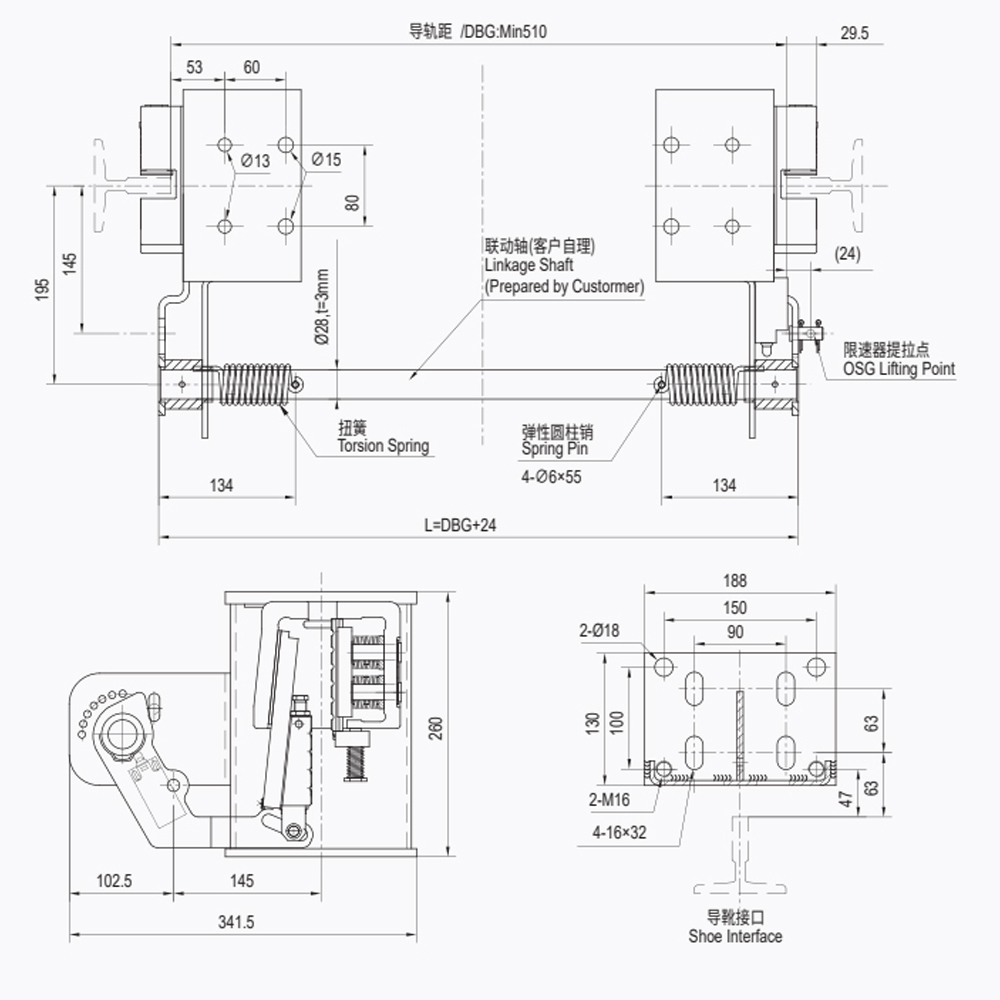
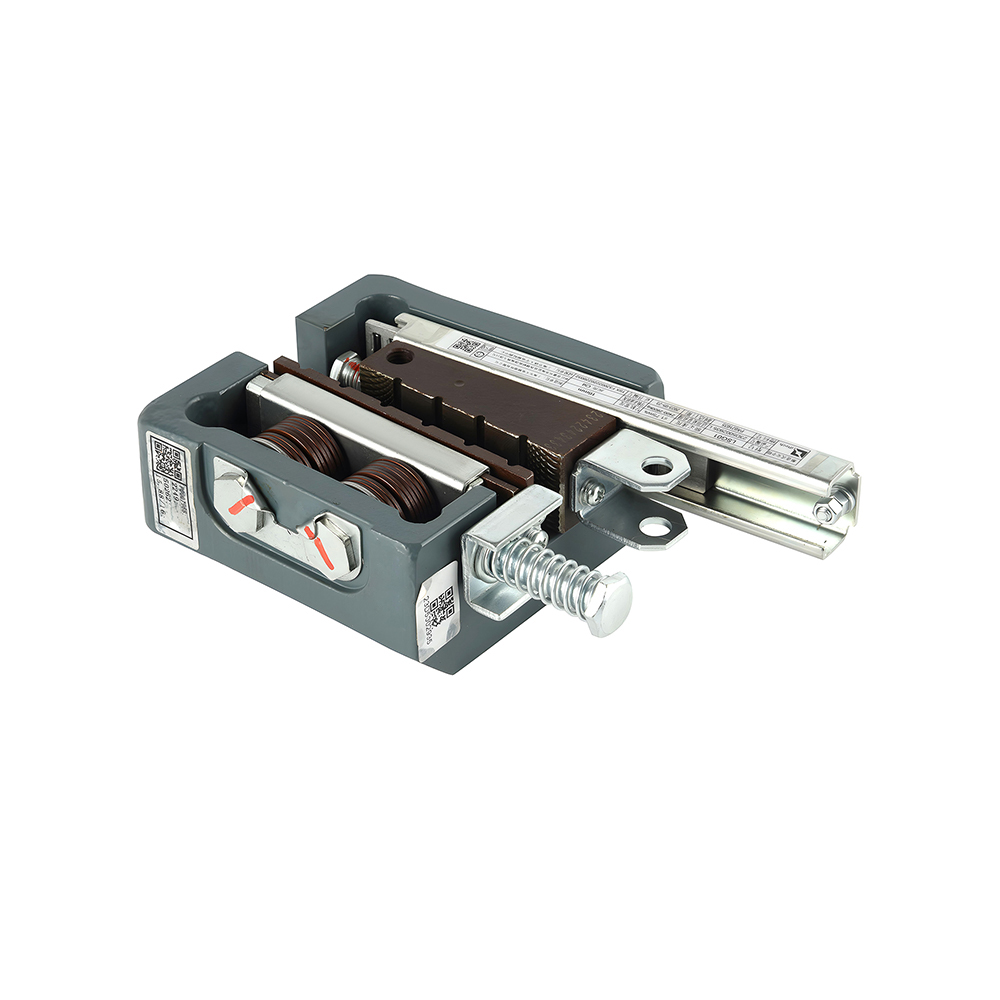
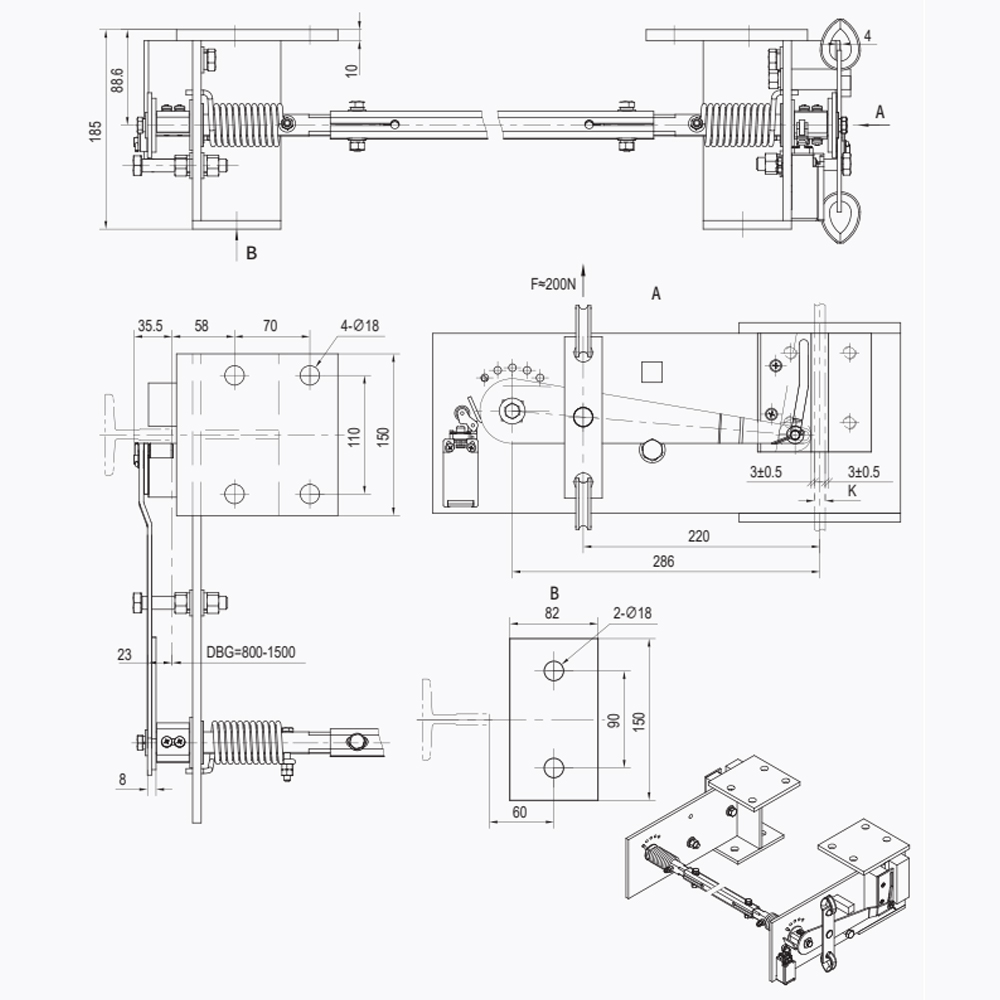
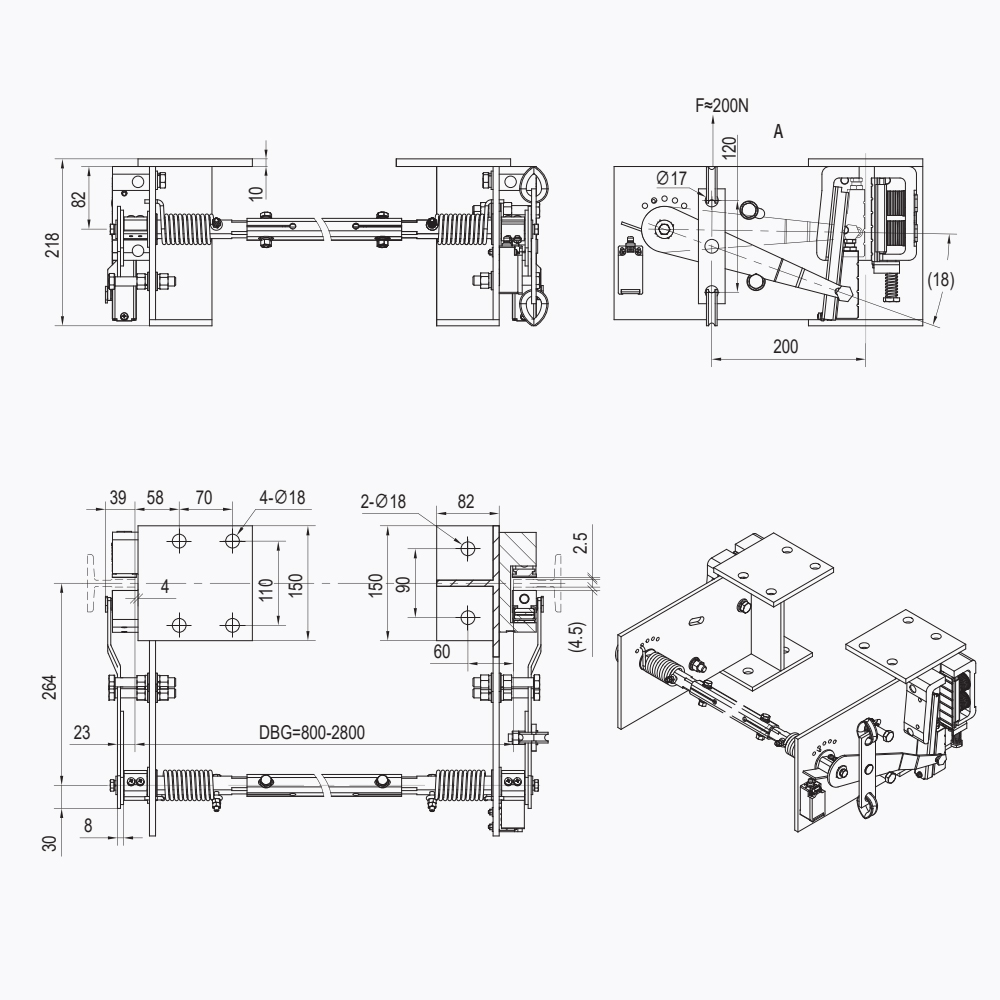
For a ready-to-install unit, engineers often evaluate a complete safety gear linkage mechanism such as the LSD03, which combines lever, rod, and lifting arms in one package with defined adjustment points.
 Wholesale LSD03 Elevator Safety Gear Linkage Mechanism Suppliers, ManufacturersShanghai Liftech Elevator Accessories Co., Ltd is China Wholesale OEM LSD03 Elevator Safety Gear Linkage Mechanism Suppliers and Manufac...View Product →
Simultaneous Engagement Is Non-Negotiable
A safety gear engages correctly only if both wedge sets touch the rail at almost the same moment. If one side engages first, the car twists about the guide rails, clamping force becomes asymmetric, and the deceleration profile changes. Progressive safety gears are tuned for a specific deceleration range; a skewed engagement pushes the car outside that range and can damage the rail surface.
The connecting rod is the component that guarantees synchronization, because it is a single rigid element linking the left and right mechanisms. This is why the linkage is not merely a trigger – it is a precision mechanical assembly with measurable tolerances.
Common Linkage Configurations and When to Use Them
Direct Mechanical Lever Linkage
The most common configuration on passenger and freight elevators. The governor rope attaches to a lever, and a rod transfers motion directly to both safety gears. It is simple, reliable, and easy to adjust on site.
Governor-Triggered Systems
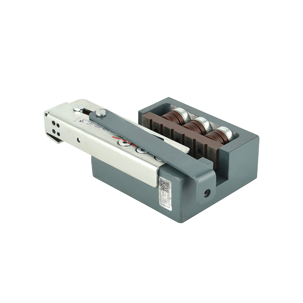
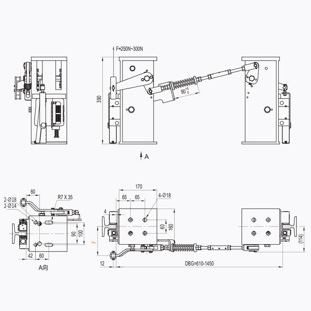
For larger cars, high-speed elevators, or systems that need a clear and repeatable trigger point, a centralized triggering system adds an actuation mechanism between the governor and the safety gears. The benefit is a more consistent stroke and simpler trip-point adjustment. A typical example is a governor-triggered safety gear system, where the governor response is translated through a single actuator before it reaches the wedge lifting arms.
 Wholesale LSD07 Governor-Triggered Safety Gear System Suppliers, ManufacturersShanghai Liftech Elevator Accessories Co., Ltd is China Wholesale OEM LSD07 Governor-Triggered Safety Gear System Suppliers and Manufactu...View Product →
Release and Reset Devices
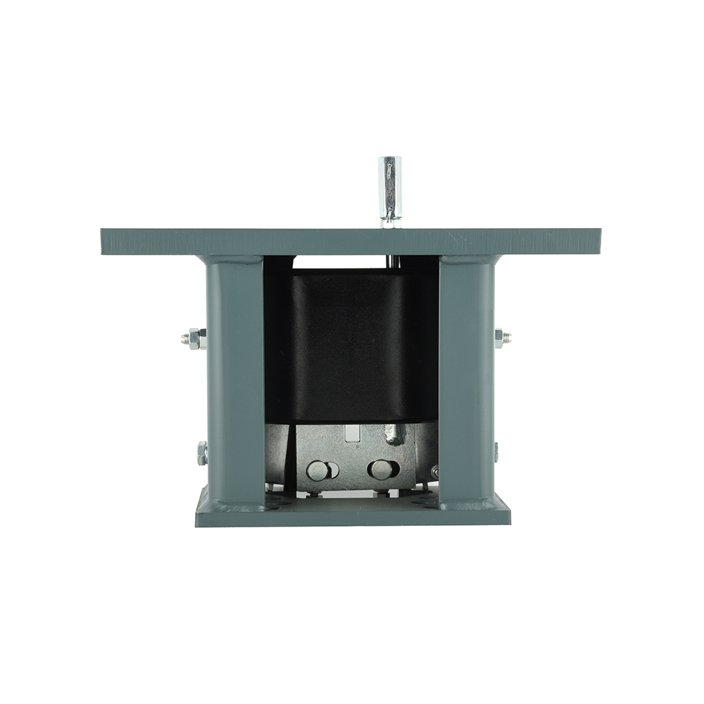
After a safety gear trip or a periodic test, the wedges must be released without forcing the rail or bending the linkage. A dedicated safety gear release device provides a controlled return path for the lifting arms, preventing wedges from remaining partially engaged under load. Release devices matter most for maintenance teams and for lifts that undergo frequent load testing.
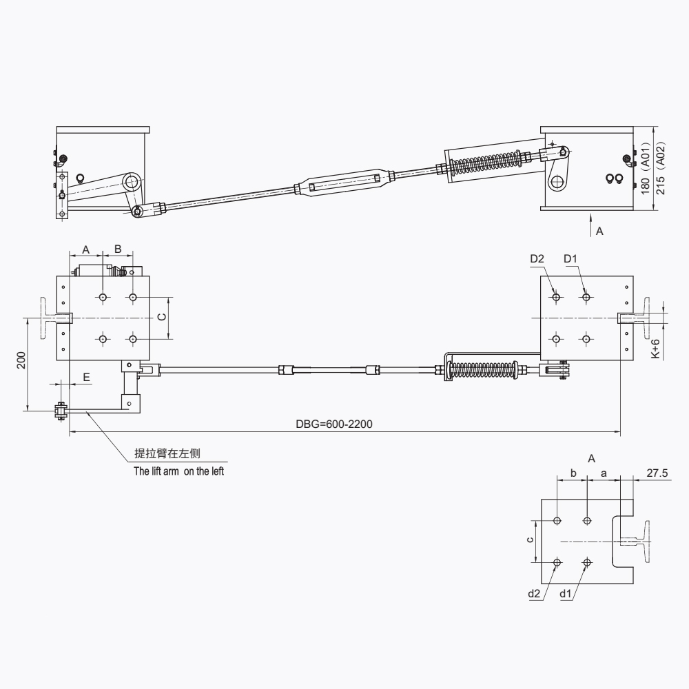 Wholesale LSD12 Lift Safety Gear Release Device Suppliers, ManufacturersShanghai Liftech Elevator Accessories Co., Ltd is China Wholesale OEM LSD12 Lift Safety Gear Release Device Suppliers and Manufacturers. ...View Product →
| Configuration | Trigger source | Typical application |
|---|---|---|
| Direct lever linkage | Governor rope arrest | Standard passenger and freight lifts |
| Governor-triggered system | Centralized actuator | High-speed cars, large capacities, UCMP integration |
| Release / reset device | Manual or external reset | Post-trip release and periodic load tests |
Design Factors That Decide Triggering Reliability
When the linkage fails, it fails at the moment of maximum load. Small design decisions – pin material, lever ratio, rod stiffness – become the difference between a controlled stop and a free-fall into the buffer.
- Trigger stroke and lever ratio. The governor produces a limited rope pull; the lever must multiply it enough to lift the wedges, but not so much that the wedges over-travel and hit the limit bolt early.
- Pivot friction and wear. Unhardened pins or unbushed holes develop play over time. Play means lost stroke and delayed engagement.
- Synchronization tolerance. The difference in lifting stroke between the two sides must be checked during installation; a deviation of more than a few millimeters increases the risk of rail damage and asymmetric deceleration.
- Corrosion protection. The linkage lives on the car top or counterweight, where humidity, dust, and condensation are common. Zinc-plated or galvanized components extend service life significantly, especially in semi-outdoor or basement shafts.
- Reset repeatability. After each trigger and reset, the mechanism must return to the same neutral position. A linkage that binds or shifts after a trip will behave differently on the next event.
What to Verify Before Sourcing a Linkage Device
For an elevator manufacturer, installation contractor, or maintenance company buying linkage components, the checks below are the minimum for a safe and compliant installation.
| Parameter | What it affects | Typical verification method |
|---|---|---|
| Connecting rod travel | Whether wedges reach full clamping | Measure stroke along the rod axis on a test rig |
| Lever ratio | Force needed to trigger the safety gear | Calculate from the drawing, confirm with the supplier |
| Synchronization deviation | Risk of car tilt on engagement | Car-top trip test with rail marks on both sides |
| Anti-corrosion coating | Lifespan in humid shafts | Request the salt spray test report |
- Interface compatibility. The linkage must match the safety gear model and the car frame layout. The same safety gear can have different linkage versions for a side-mounted or center-mounted governor rope.
- Adjustability. Look for slotted bolt holes, adjustable rod ends, and a clearly marked neutral position; these features reduce installation time and make field adjustment possible.
- Test evidence. The linkage is validated as part of the safety gear assembly. Ask for the trip test record, the wedge drop test report, and the certificate of conformity for the complete assembly, not just the linkage part.
A practical starting point is to compare the linkage layout against the design of the elevator safety gear and its working principle, then check the governor connection and linkage functions to confirm the stroke and force match.
Standards and Compliance Considerations
The linkage device is not normally certified as a standalone component. International and regional standards – EN 81-20 / EN 81-50, GB 7588, and similar – test the safety gear as part of the car safety circuit. The trip, drop, and reset procedures all exercise the linkage, so the linkage is already included in the safety gear's certified performance envelope.
When you source a linkage separately, ensure the supplier can provide:
- The safety gear model and serial number it was tested with;
- The governor model with which the stroke was calibrated;
- The adjustment instructions and the nominal trigger force.
Because the overspeed governor determines the available rope pull, the linkage must be designed with that force in mind. A mismatch between governor output and linkage stroke is one of the most common compatibility errors on the market.
Conclusion: The Linkage Is Where Safety Is Confirmed
An elevator safety gear is only as good as the mechanism that triggers it. The linkage device transmits the governor's decision, synchronizes both wedge sets, and makes the system resettable. These three functions are measurable and testable – but only if the component is designed, sourced, and adjusted with the same rigor as the safety gear itself.
When evaluating a supplier, look beyond the part number. Ask for tested assembly evidence, confirm the stroke and lever ratio, and verify material and coating quality. If the linkage works, the safety gear works; if the linkage fails, nothing else in the chain stops the fall. For engineers and buyers, that makes the elevator safety gear linkage device a critical purchasing decision, not an accessory.